
Product Introduction
HackRF Pro is the core RF transceiver unit that performs the actual receiving and transmitting; PortaPack H4M Pro is the handheld touch panel that stacks on top of it and runs the open-source Mayhem firmware, turning the combination into a self-contained handheld software-defined radio that operates completely offline, without a computer.
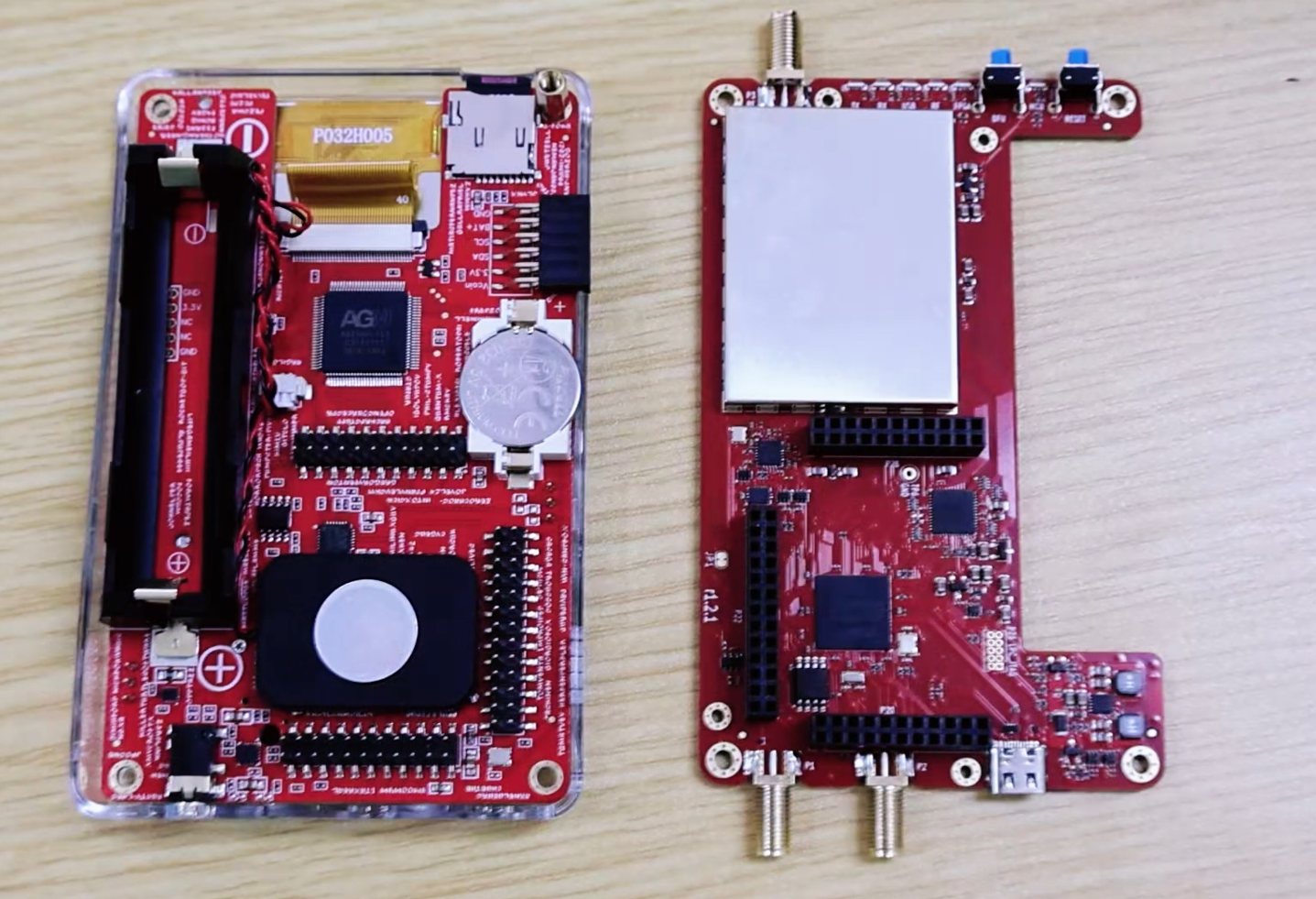
Compared with the classic HackRF One, HackRF Pro upgrades the main MCU, replaces the CPLD with an iCE40 UltraPlus FPGA, quadruples the onboard flash, adds a built-in 25 MHz 0.5 ppm TCXO, extends the lower frequency limit down to 100 kHz, moves to a USB-C connector, and adds reinforced internal RF shielding together with enhanced antenna surge protection. The PortaPack H4M Pro side moves from a flat polymer cell to a standard 18650 cylindrical battery, repositions the speaker and the SD-card slot, and carries an anti-counterfeiting silkscreen pattern on the front PCB.
The unit ships pre-loaded with Pro_v2.4.0, a modified build of Mayhem v2.4.0. Users are free to update to official Mayhem releases, including nightly builds that carry the HackRF Pro adaptations.
Product Composition
HackRF Pro VS HackRF One
The three items that matter most in daily use are the frequency floor, the clock and the flash size. The 100 kHz floor makes medium-wave AM and shortwave reception possible without an external upconverter. The 0.5 ppm TCXO removes the frequency drift that forces constant retuning on an untrimmed HackRF One, which is what makes narrow-band digital decoding such as POCSAG and ADS-B reliable. The 32M-bit flash is what allows the full Mayhem application set to be resident on the device.
PortaPack H4M Pro Hardware Updates
The battery connector is changed from a 104050 polymer lithium-ion pack to a standard 18650 cylindrical cell, so a depleted cell can be swapped in the field instead of being recharged in place.
The front PCB carries a redesigned silkscreen with an anti-counterfeiting pattern.
Developer names are added on the back PCB.
The speaker and the microSD card slot are repositioned, so the card can be removed without disassembling the stack.
Hardware Specifications
Half-duplex is an architectural property of the HackRF signal path, not a firmware limitation. Any experiment that appears to receive and transmit at the same time — for example the transmit-receive verification tests in Chapter 9 — requires two units.
Operating Modes and Connection Methods
Required Drivers and Software Dependencies
Device Preparation and SD Card Resource Deployment
This chapter covers everything that must be done before the first power-on: assembling the two boards, installing and calibrating the battery, choosing an antenna, and deploying the Mayhem resource package to the SD card. Every later chapter depends on this one being completed correctly.
Assembly
Align the PortaPack H4M Pro with the HackRF Pro expansion header and press the two boards together evenly, keeping them parallel throughout. Do not rock the panel from one end, which bends the header pins. When seated correctly the two boards sit flush with no visible gap along the connector.
Battery Installation and Capacity Calibration
Step 1 · Battery installation
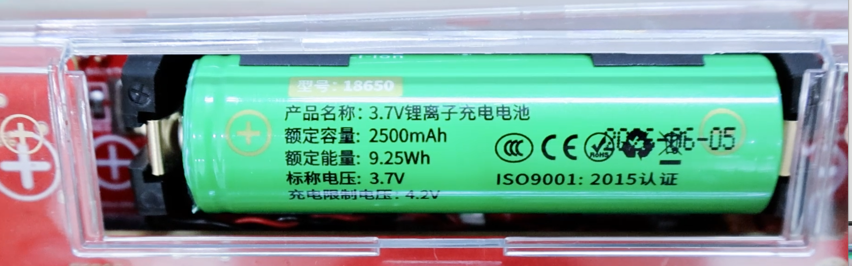
Open the battery compartment on the back of the PortaPack H4M Pro and install a 3.7 V 2500 mAh 18650 cell strictly according to the plus and minus marks moulded into the holder. Never reverse the polarity — it will burn the power-management chip.
Step 2 · Capacity calibration
After powering on, tap the battery icon at the top right of the title bar to enter its settings, change the default 1500 mAh to the actual 2500 mAh, and save. From then on the title bar reports remaining percentage, real-time voltage and estimated runtime accurately.
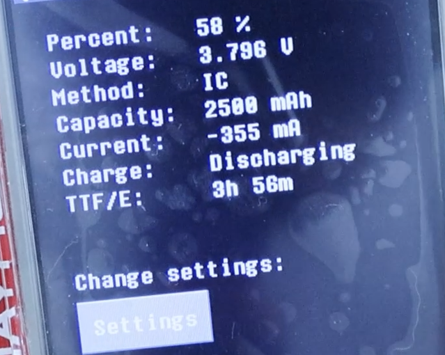
The capacity value is only a reference figure used by the fuel-gauge calculation. Leaving it at 1500 mAh with a 2500 mAh cell installed does not damage anything, but the percentage reading and the runtime estimate will both be wrong.
Charging and Precautions
Step 1 · Charging
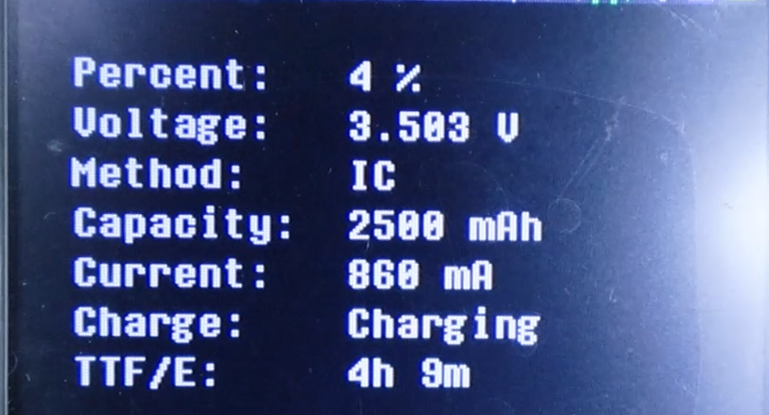
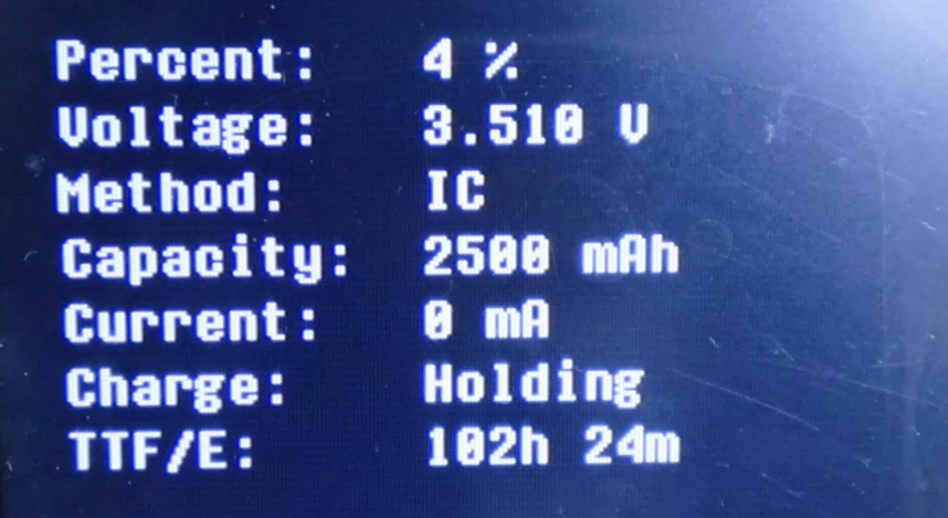
Connect the device to a USB power source with a USB cable to start charging. Tap the battery icon to check the status: the charge field reads charging while the cell is being charged.
Step 2 · Precautions
The power switch must be on while charging. If the switch is off, the charge field shows holding and the cell will not charge. This is the single most frequently reported "battery is dead" problem, and it is not a fault.
SD Card Formatting Standard
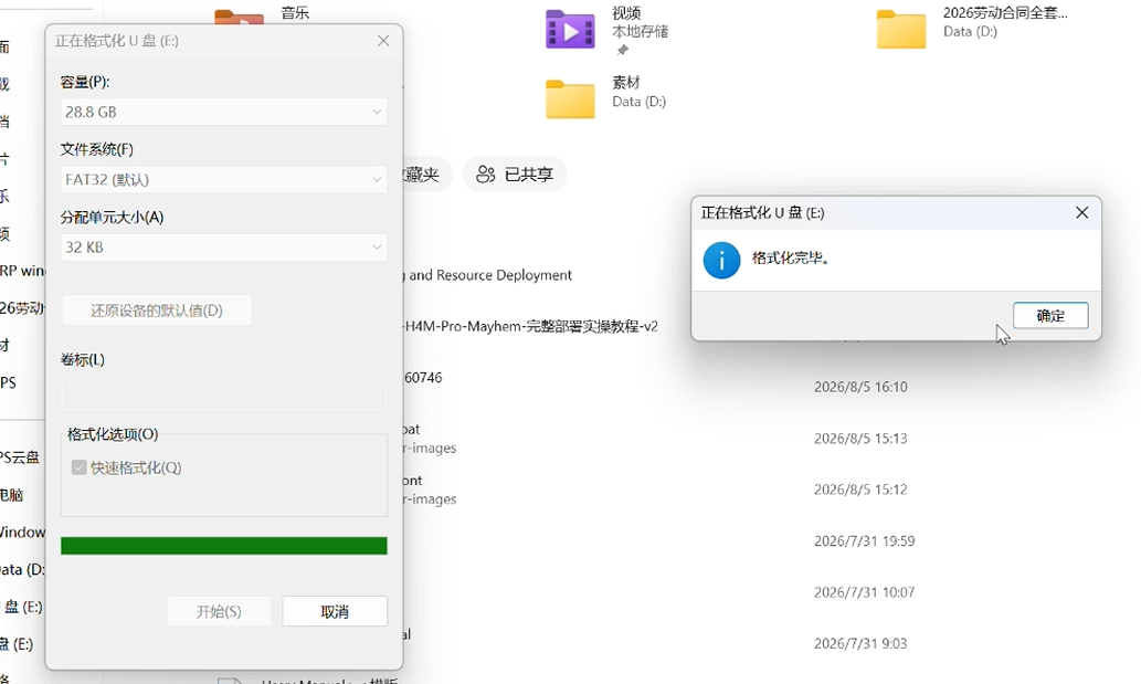
Use a Class10 / A1 microSD card and format it as FAT32 or exFAT. Low-quality or worn cards are the root cause of two distinct failures: packet loss during IQ recording, which silently corrupts a capture, and flashing failure, which can leave the unit unbootable.
Mayhem Resource Deployment
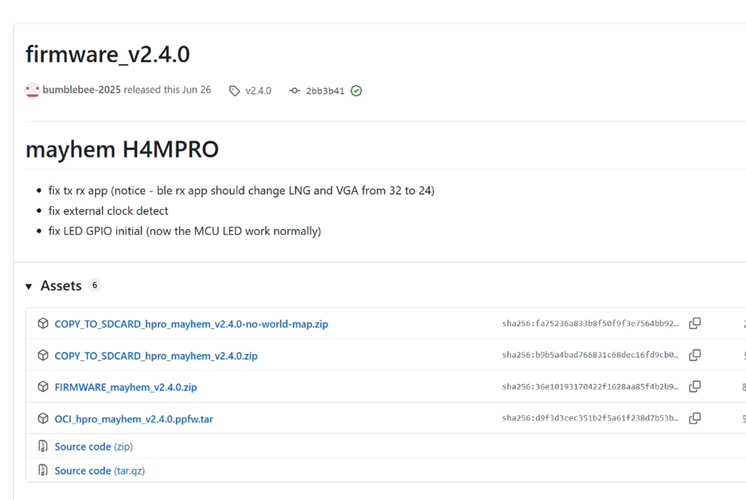
From the Mayhem release page, download the package whose name ends in COPY TO SDCARD, decompress it, and copy all of its folders directly to the SD card root. Do not nest them inside a sub-folder — the firmware looks for these directories at the root and nowhere else.
https://github.com/OpenSourceSDRLab/mayhem-firmware/releases
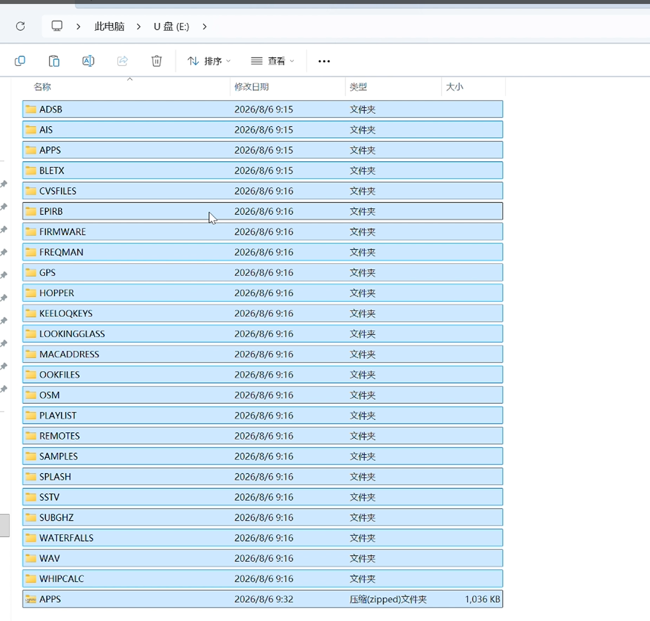
Directory core functions:
The resource package must be redeployed every time the firmware is updated. A version mismatch between the two shows up as greyed-out application icons on the main menu.
Firmware Flashing and Boot Verification
Three flashing schemes are provided for different situations, followed by the standard boot self-test that determines whether a flash succeeded.
Firmware File Types
Choosing a Flashing Method
Method 1: Offline Flash via SD Card
Step 1 · Copy the firmware
Copy the firmware file to the SD card root.
Step 2 · Flash on the device
Insert the SD card, power on, then go to Main menu → Utilities → Flash Utility, select the firmware file and confirm to start automatic flashing.
Step 3 · Completion
The screen flashes continuously during the write. The unit restarts by itself once the write-success prompt appears. Highlighted, clickable external application icons on the main menu confirm that the firmware and the SD-card files are at matching versions.
Do not switch the unit off and do not remove the SD card while the screen is flashing. An interrupted write is exactly the condition that Method 3 exists to recover from.
Method 2: WebUSB Browser Online Flash
Step 1 · Driver
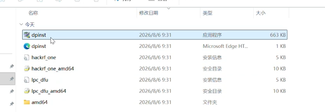
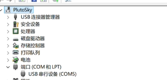
Run dpinst.exe from the supporting resource package to install the USB driver for HackRF Pro. After connecting the data cable, confirm that a new COM port appears in Device Manager.
Step 2 · Browser connection
Open Chrome or Edge and go to https://hackrf.app. Connect HackRF Pro over USB and allow WebUSB access in the browser prompt. The page then shows "Device Connected".
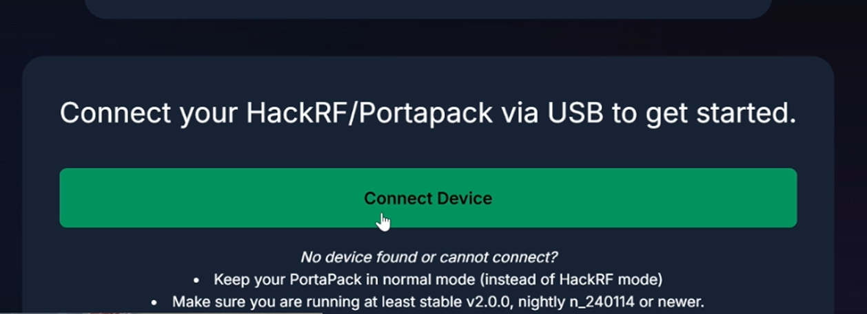
Step 3 · One-click flash
Go to Manage Firmware, choose stable, nightly, or a custom local file, and click upload. The indicator flashes during the transfer, then stops, and the device restarts to finish.
Method 3: DFU Batch Full Recovery
This is the brick-rescue path. Before starting, run dpinst.exe to install the matching USB driver for HackRF Pro.
Step 1 · Enter DFU mode
Hold the HackRF Pro DFU key, plug the USB cable into the computer, then release the DFU key. In DFU mode all HackRF Pro indicator lights go fully dark — this differs from HackRF One and is the correct indication, not a fault.
Step 2 · Run the batch script
Open the flashing directory and run mayhem_flasher.bat:
Enter 3 → select [HackRF Pro / PortaPack] hardware
Enter 2 → select [Flash DFU then full Mayhem one-click recovery]
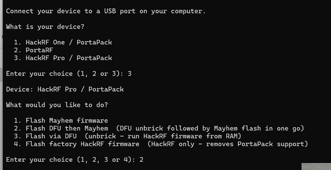
Wait for the terminal to print Firmware flashed successfully.
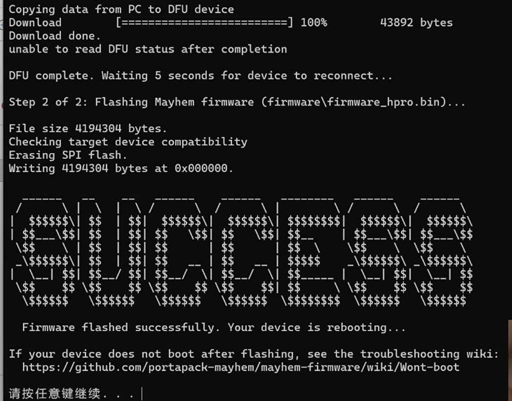
Step 3 · Recovery judgment
The MCU, FPGA and RF indicator lights all light up, the device restarts by itself into Mayhem, and the red FLASH ERR prompt no longer appears at the bottom left of the boot screen.
Post-flash Boot Self-test
Normal boot criteria — all four must hold:
1. The bottom left shows the full firmware version, with no red FLASH ERR.
2. The top-right SD icon is green, meaning the card is recognised.
3. All main-menu application icons are bright and open normally.
4. The bottom-right clock shows real-time UTC.
Abnormal prompts:
Touch Calibration and the Main Interface
An uncalibrated resistive touch panel makes every subsequent operation unreliable, so calibration comes first. The rest of this chapter reads the title bar and the main menu so that device status can be judged at a glance.
One-click Touch Calibration
Step 1 · Enter calibration
Main menu → Settings → Calibration.
Step 2 · Four-point calibration
Tap each cross target in sequence as prompted, holding each point for at least one second before releasing. Releasing too early is the usual reason calibration data comes out inaccurate.
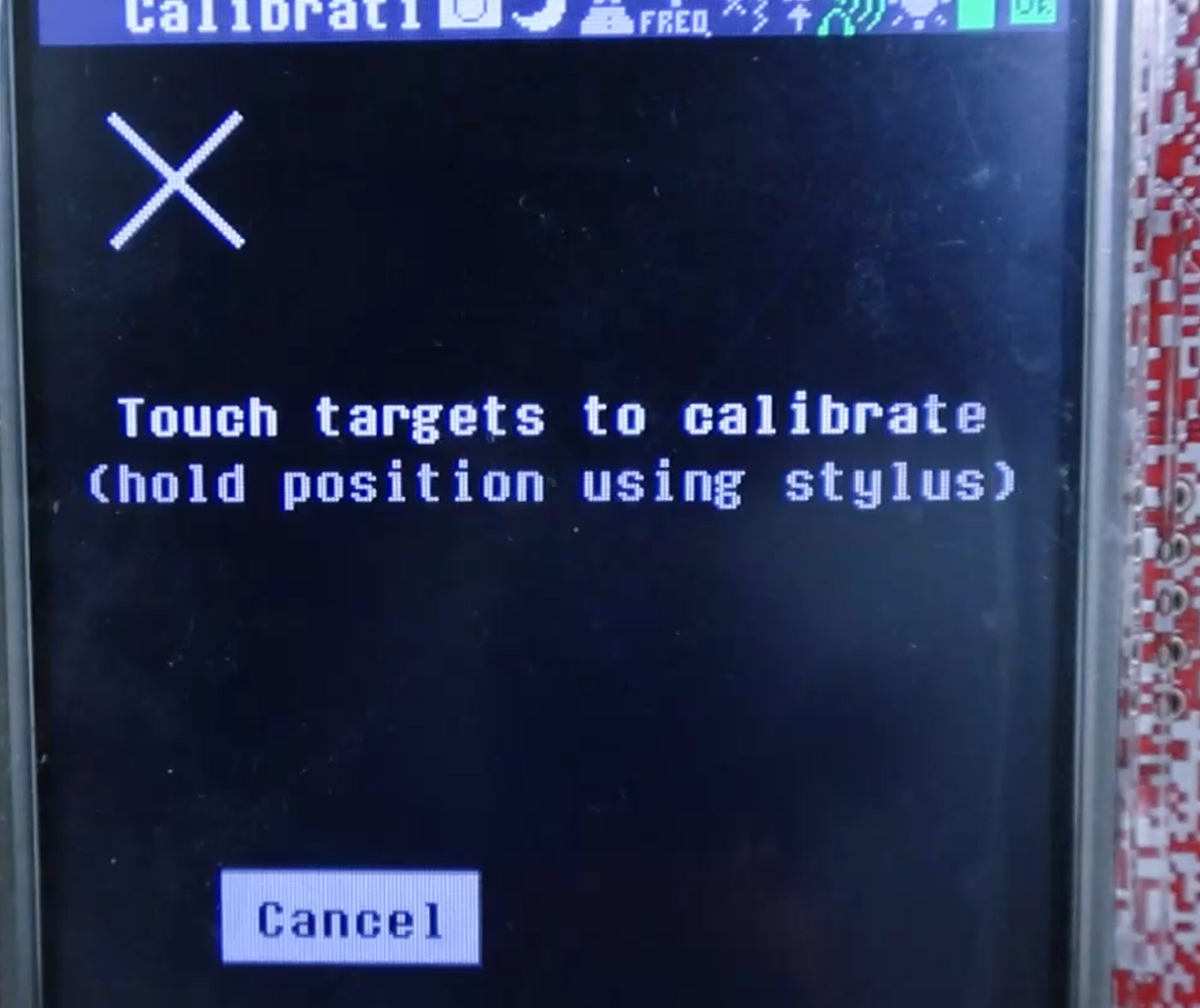
Step 3 · Troubleshooting
If the touch is still offset after a restart, the internal coin cell is depleted. Replacing it makes the calibration persist permanently — otherwise the calibration is lost at every power cycle.
Title-bar Status Icons
From left to right along the right-hand side of the title bar: screenshot, sleep, stealth mode, frequency converter, Bias-Tee DC feed, external clock output, mute, screen brightness, battery percentage, SD-card status.

Bias-Tee warning. The Bias-Tee icon turns yellow when the feed is on, and the antenna port then outputs 3.3 V DC. Enable it only with an active antenna or an external LNA attached. Never enable it with a passive antenna — this is the one title-bar toggle that can damage hardware.
Main Menu Modules
All functions are grouped into eight core modules.
Information Bar Status
The left side of the information bar shows the current Mayhem firmware version, or a red FLASH ERR if the firmware is damaged. The right side shows real-time UTC date and time. The clock stops when the coin cell is depleted, and with no SD card inserted the date advances by one day on every restart.
Physical Controls
The 5-way rotary encoder key gives precise control where the resistive touch panel is awkward. Rotate to step a value up or down, push the four directions to move between fields, and press the centre to confirm. Frequency digits in particular are far easier to set with the encoder than by tapping.
Universal Gain, Frequency and Bandwidth Logic
Gain, centre frequency and demodulation bandwidth are the three parameters shared by every receiving app in the firmware. Learning them once makes every experiment in the following chapters straightforward.
Gain Chain Logic
The receive chain has three gain controls, and they are not interchangeable.
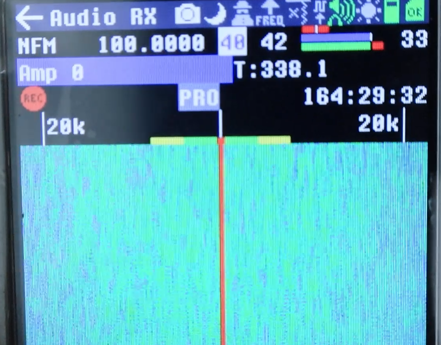
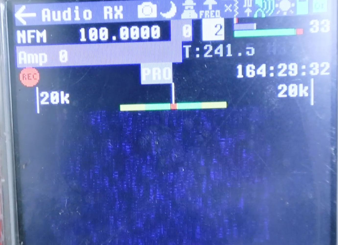
LNA and VGA raise sensitivity and are the two you normally adjust. Too high saturates the front end and the waterfall goes solid green with no structure; too low buries the signal and the waterfall goes dark blue with no line visible. AMP is the front-end RF amplifier — keep it at 0 for strong nearby signals, and reserve it for genuinely weak, distant ones.
The practical procedure is: set AMP to 0, raise LNA until a signal is visible, then trim VGA for contrast. If the display saturates, back off LNA before touching anything else.
Centre Frequency and the DC Spike
A permanent vertical line at the exact centre of the display is the HackRF DC spike and local-oscillator leakage. It is an artefact of the zero-IF architecture, not a signal. When a target sits close to the centre it can be hidden by this artefact, so the standard practice is to offset the tuned centre frequency by 50–100 kHz from the target and let the demodulation bandwidth cover it.
Demodulation Bandwidth
Bandwidth must be wide enough to contain the signal plus the transmitter's frequency error. Choosing a bandwidth that is too narrow is the more common error: a low-cost 315 MHz remote can drift tens of kilohertz, so an 8.5 kHz filter loses it while a 16 kHz filter holds it. Choosing one that is too wide costs sensitivity and lets adjacent signals in, but rarely breaks the experiment outright.
Common Band Preset Parameter Table
These values are starting points that work in typical conditions. Adjust LNA and VGA to suit the local signal environment; the demodulation mode, bandwidth and step values should be used as given.
Spectrum Scanning and FM Broadcast Reception
These are the entry-level experiments: automatic frequency search and audio demodulation, using the Recon and Audio apps. Both are receive-only and can be performed anywhere without compliance concerns.
Recon: Automatic Frequency Search and Capture
Step 1 · CONFIG page
Check "auto start scan", load a frequency-range file, and save. Select SEARCH manual-range scanning mode.
Step 2 · Scanning range
Fill in the target START and END frequencies. You must click the SEARCH button to apply them, and then confirm that the R value on the third line has updated. Entering the range without clicking SEARCH leaves the previous range active — this is the most common reason a Recon scan appears to find nothing.
Step 3 · Squelch threshold
Each band uses a fixed squelch reference: FM broadcast squelch = −50 dB, walkie-talkie squelch = −60 dB. The device automatically locks onto and records a frequency whenever the received power exceeds the threshold.
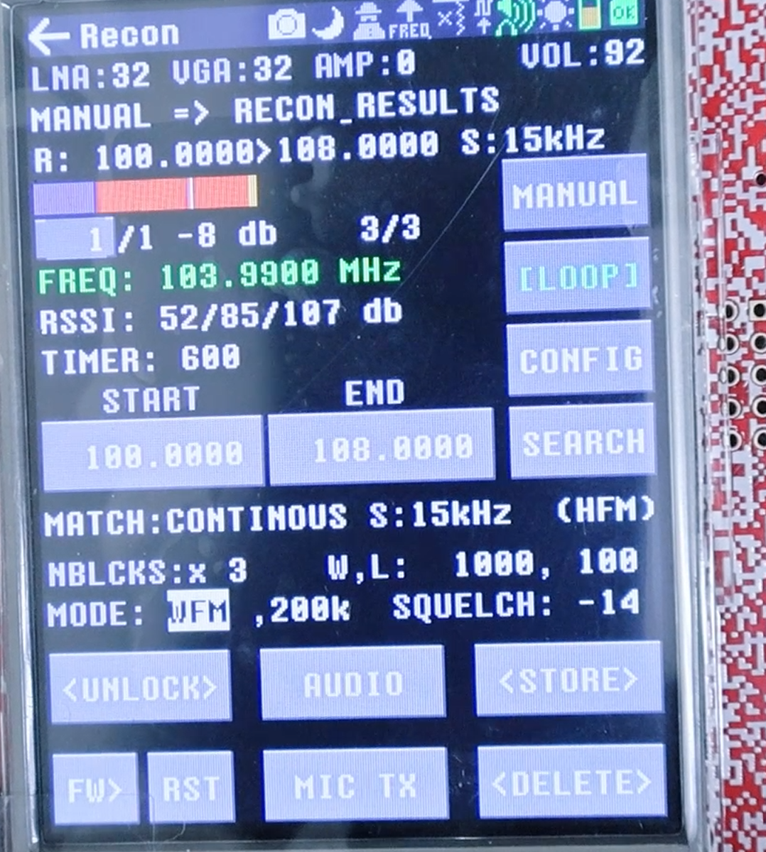
Safety. The yellow-marked options on the CONFIG page are transmit switches. Do not enable them when performing receive-only work or spectrum scanning.
WFM Broadband FM Reception
Step 1 · Audio app
Main menu → Receive → Audio, then select WFM broadband FM demodulation.
Step 2 · Core parameters
Enter a local FM frequency, for example 103.9 MHz. Bandwidth 200 kHz, LNA 16, VGA 20, AMP 0.
Step 3 · Audio playback
Adjust the volume slider on the right. The built-in speaker or a 3.5 mm headset outputs the broadcast audio.
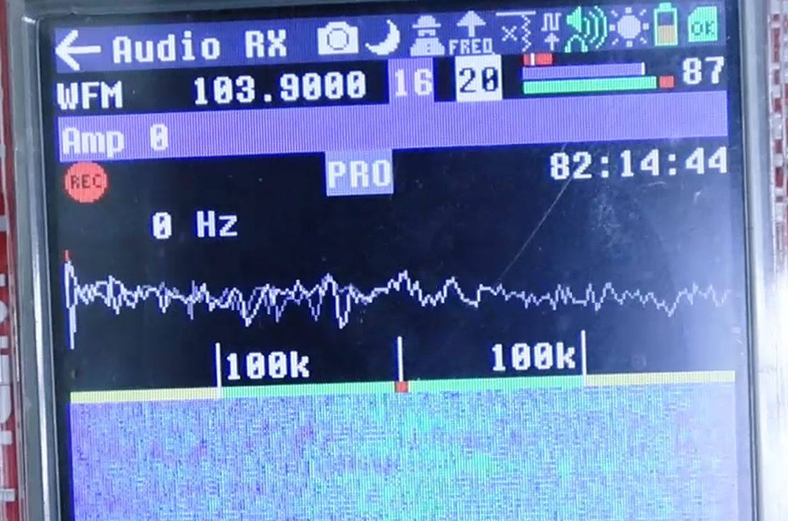
FM broadcast reception is the fastest way to confirm that the whole receive chain — antenna, RF front end, demodulator and audio output — is working. When any later experiment produces no sound at all, come back and run this test to isolate whether the fault is in the audio path or in the reception itself.
IQ Capture and Wireless Replay
This is the core offline experiment: recording raw IQ from a 315 MHz wireless doorbell and replaying it over the air to trigger the doorbell again. Spectrum positioning comes first, then recording, then replay.
Locate the Target Frequency First
You cannot record and replay a signal until you know its exact frequency, so locating it is step one.
Step 1 · Parameters
Main menu → Receive → Looking Glass. MIN start = 300 MHz, MAX end = 450 MHz, LNA = 16, VGA = 20, AMP = 0, bip tone ON.
Step 2 · Signal identification
Press the doorbell button repeatedly while watching the waterfall. The line that flashes in sync with your presses is the target — this synchronisation is what distinguishes it from ambient interference.
Step 3 · Narrow-range precise positioning
Set MIN = 305 MHz and MAX = 325 MHz to zoom into the 315 MHz region, then move the MARKER cursor onto the line to read the accurate centre frequency, in this case 315.000 MHz.
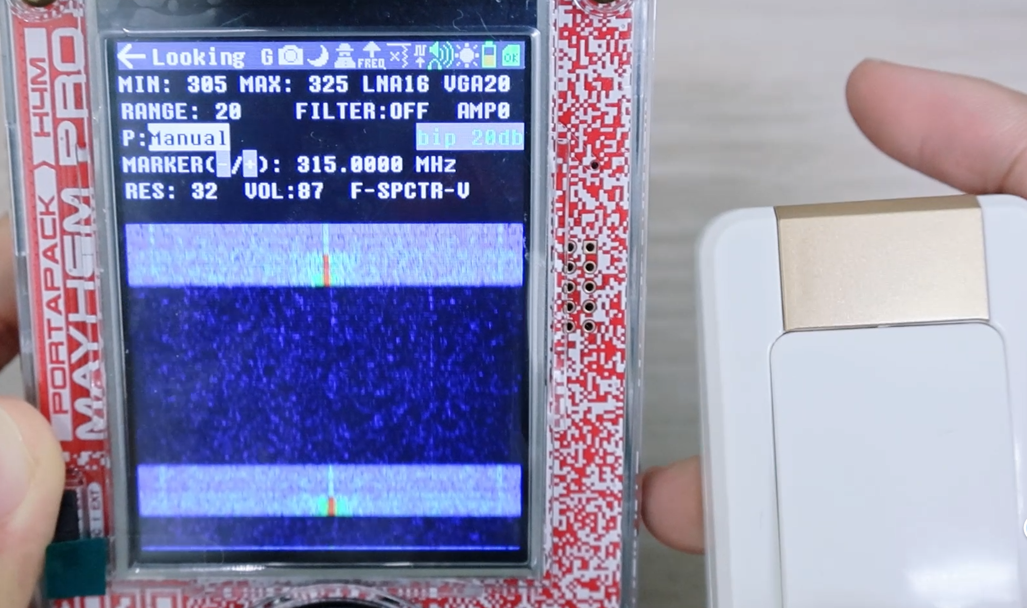
A full-screen green waterfall means the gain is too high and the front end is saturated. A full-screen dark blue with no line means the gain is too low — raise LNA and VGA moderately.
Capture Recording Parameters
Step 1 · Enter Capture
Main menu → Receive → Capture. Fill in the accurate centre frequency measured during the spectrum scan, 315.000 MHz.
Step 2 · Fixed recording parameters
Sampling rate = 500 kHz, which gives the best replay compatibility. LNA = 16, VGA = 32, AMP = 0. Choose the normal-coloured record gear and avoid the yellow high-speed gears, which cause packet loss.
Step 3 · Recording procedure
Press the red record button first, then press the doorbell 2 to 3 times. Keep packet loss at 0% throughout; if packet loss appears, lower the sampling rate or use a faster SD card. Click stop once the complete signal has been captured.
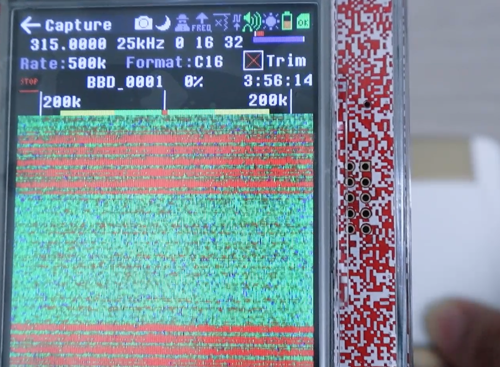
Recording the doorbell more than once in a single capture is deliberate. If one press is clipped at the start or end of the file, another complete copy is still present in the recording.
Recording File Format and Metadata
Files are saved to the CAPTURES folder on the SD card. Each recording generates two files that must be kept together:
If only the .C16 is kept and the .TXT metadata is deleted, Replay cannot automatically match the correct transmit parameters. When copying captures to a computer for archiving, always copy both.
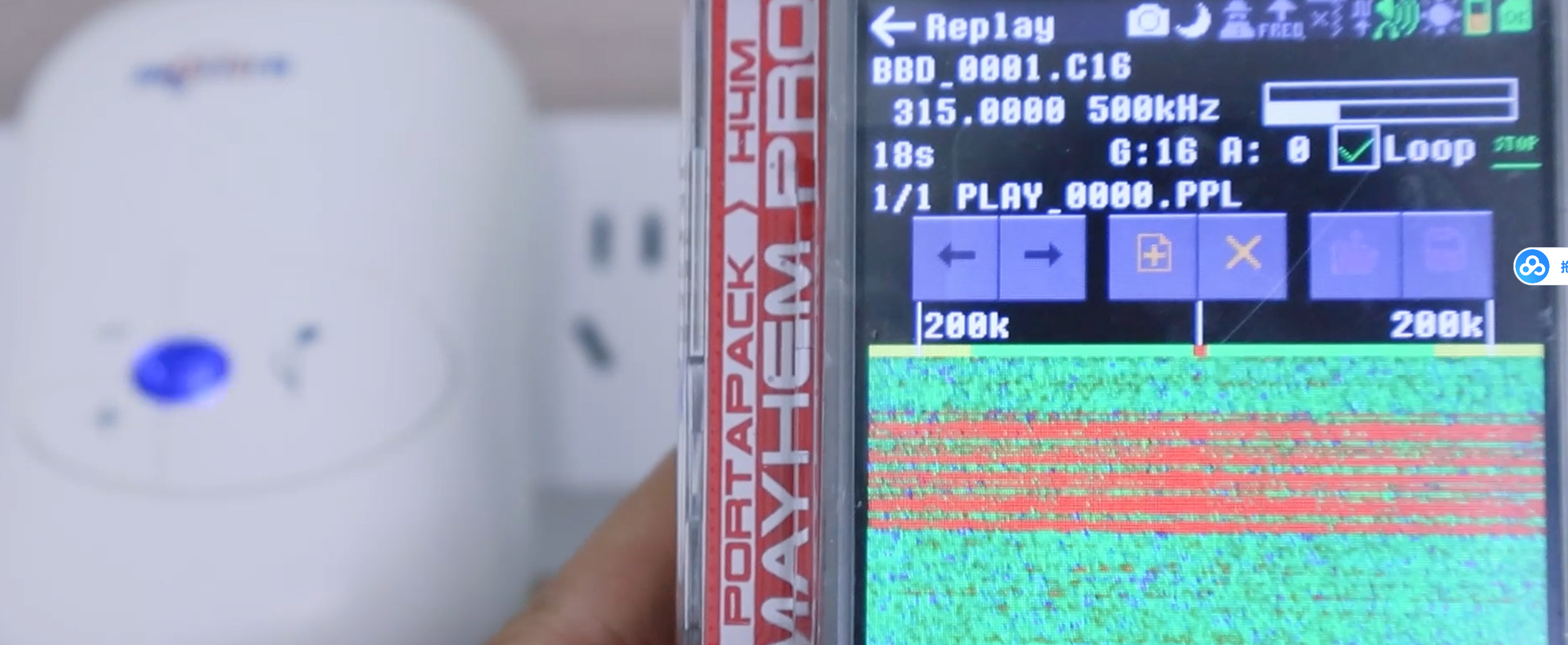
Replay Transmit Parameters
Step 1 · Enter Replay
Main menu → Transmit → Replay. Click Add file and select the .C16 file in CAPTURES.
Step 2 · Core transmit parameters
The frequency and sampling rate load automatically from the .TXT metadata — verify that they match the recording. Set transmit gain G =16.
Step 3 · Loop switch
Leave Loop unchecked for a single trigger; check it for continuous cyclic transmission.
Press play to transmit. The physical doorbell rings, and the record-to-replay loop is complete.
Factors That Decide Replay Success
When a replay does not trigger the target device, the cause is almost always one of the following, in order of frequency:
1. The `.TXT` metadata is missing, so the sampling rate and frequency do not match the recording.
2. The recording contains packet loss, so the captured waveform is corrupted. Re-record with 0% loss.
3. The centre frequency was read imprecisely during the spectrum scan. Re-measure with a narrow Looking Glass span.
4. The transmit gain is too low, or the antenna is missing or wrong for the band.
5. The recording captured only part of a transmission. Record several button presses in one file.
Audio RX of a 315 MHz Doorbell and Troubleshooting
This chapter listens to the same doorbell as audio, which is a far more demanding test of the receive chain and exposes a set of characteristic problems worth understanding.
OOK Modulation and Mode Selection
A 315 MHz doorbell uses OOK/ASK — on-off keying. The carrier has only two states, present and absent, and carries no frequency modulation at all.
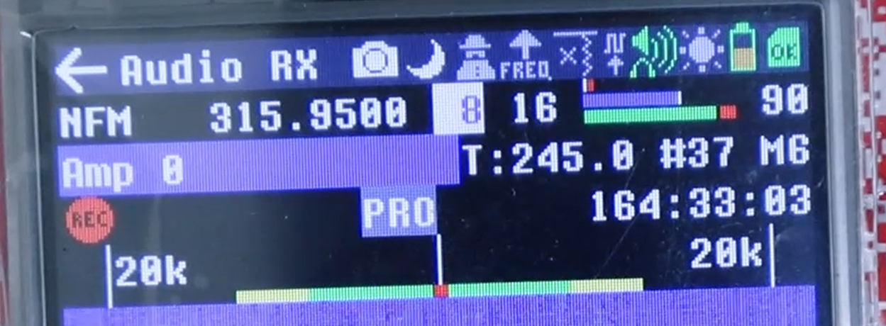
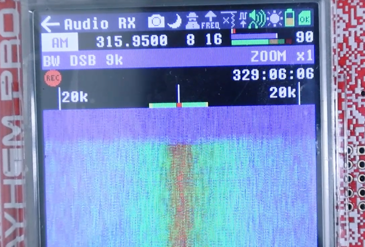
An FM discriminator outputs a DC level for an unmodulated carrier, and that DC is then removed by the audio path through DC blocking, de-emphasis and band-pass filtering. In NFM you therefore hear only the weak pulses that leak through at each on/off transition, not a clean tone. This is expected behaviour, not a fault, and it is why AM gives crisper audio for this signal even though NFM is perfectly adequate for verifying that the carrier is present.
Antenna and Parameter Settings
Step 1 · Antenna and distance
Extend the ANT500 to about 23 cm. Keep the doorbell button 1 to 3 m away from the unit — pressing it against the device drives the front end into saturation.
Step 2 · Enter Audio RX
Main menu → Receive → Audio RX, then set the parameters below.
Operation and Signal Interpretation
Press and hold the doorbell button, then check the three criteria below.
Switching to AM mode at this point yields distinct popping sounds instead of the rasp.
Troubleshooting Quick Reference
Digital Protocol Transmit and Receive Verification
This chapter verifies four representative digital protocols supported by the Mayhem firmware: APRS, POCSAG, BLE and ADS-B. APRS, POCSAG and BLE are tested as two-unit transmit-receive pairs, because the hardware is half-duplex and a single unit cannot verify itself. ADS-B is receive-only and decodes real aircraft traffic with one unit.
Common Procedure and Safety Notes
Safety and compliance
1090 MHz is the aviation surveillance frequency. Radiating a fabricated aircraft track into real airspace is illegal and a genuine flight-safety hazard, so ADS-B is treated as a receive-only experiment throughout this manual and no ADS-B transmission is performed.
144.390 MHz falls inside the amateur radio band, where transmitting requires the corresponding licence. The three transmit tests must be run by conduction — connect the two units with an RF cable through a 30–40 dB attenuator, or work inside a shielded enclosure. Do not fit antennas and radiate into open space, and keep the gain at the lowest workable value.
Common procedure, applicable to APRS, POCSAG and BLE
Step 1 · Configure the receiver first
Switch the receiving unit to the Receive interface, select the RX mode for the protocol under test, then set the frequency and gain. Always configure the receiver before the transmitter, otherwise the first frames are missed.
Step 2 · Then configure the transmitter
Open the Transmit interface on the transmitting unit, enter the TX page for the same protocol, set an identical frequency, and fill in the payload or parameters.
Step 3 · Transmit and verify
Start transmitting and read the decoded result on the receiver. The test passes when the received content matches what was sent.
APRS Transmit-Receive Test
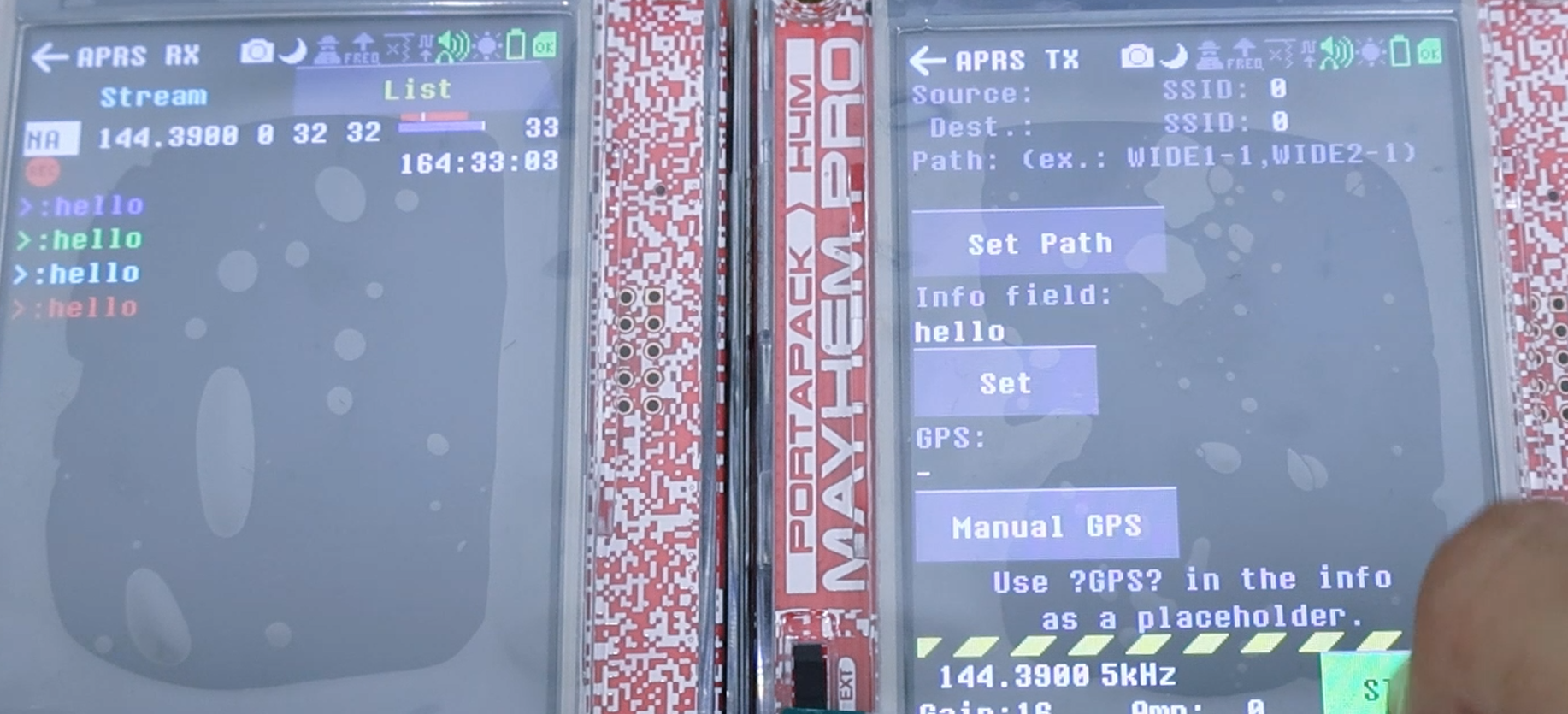
APRS is tested at 144.3900 MHz, and both units must be set to exactly the same frequency.
Configure the receiver first: open APRS RX and leave the gain at its default value. Then configure the transmitter: open APRS TX, set the SSID to any value you like, tap Set to open the message editor, type the content you want to send, and confirm with OK.
Start transmitting and read the result on the receiving unit. The test passes when the receiver decodes the frame in real time and displays message content exactly identical to what was entered on the transmit side.
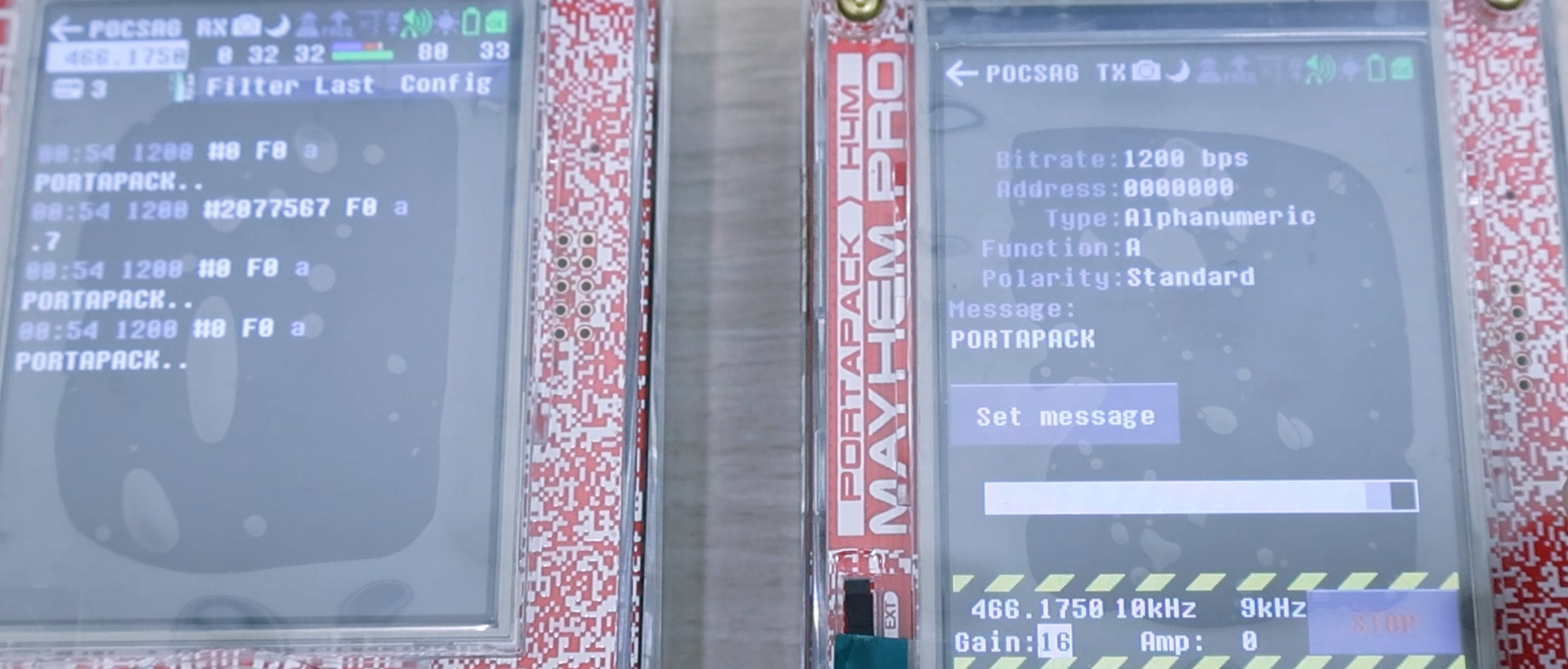
POCSAG Transmit-Receive Test
POCSAG does not require a specific frequency; the only condition is that the receiving and transmitting units are set to the same one.
Open POCSAG RX on the receiver with the gain left at its default value, then open POCSAG TX on the transmitter and set the identical frequency. On the transmit page, set the message type to Alphanumeric and keep the built-in default payload PORTAPACK.
Start transmitting: the receiver should decode the frame and display the word PORTAPACK on screen, and seeing that string is the pass criterion for this test.
The message type is the one setting that decides the outcome here. With any type other than Alphanumeric, the default PORTAPACK payload will not be decoded into readable text and the receiver shows numeric or blank content — even though the link itself is already working. If you see the frame arrive but not the word, check the message type before changing anything else.
BLE Transmit-Receive Test
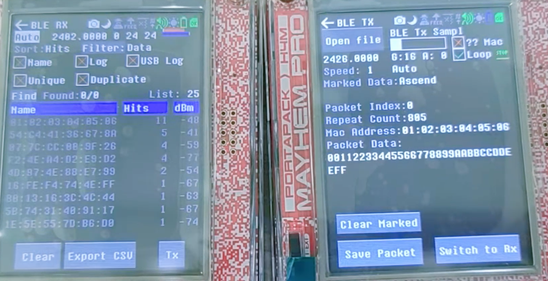
BLE is tested on the 2.4 GHz advertising channels 37, 38 and 39.
On the receiving unit, open BLE RX, set the mode to Auto so that it hops across all three advertising channels, set Sort to Hits so that the most frequently seen device rises to the top of the list, and set the gain to 24. Tap clear before every run to flush the entries left over from the previous test.
On the transmitting unit, open BLE TX, use Open file to import any file as the advertising payload — the file content itself is irrelevant to the result — then set the transmit gain to 16 and enable Loop so that the packet is broadcast continuously.
The test passes when the MAC address 01:02:03:04:05:06 keeps hitting at the top of the receiver list.
ADS-B Receive-Only Test
ADS-B is the only receive-only test in this chapter, and a single unit is enough.
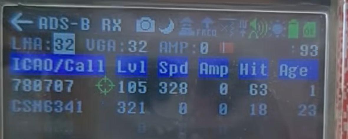
Switch to the Receive interface, select ADS-B mode, set both LNA and VGA to 32 as the starting reference, then wait a moment. Aircraft within range normally appear in the list within seconds.
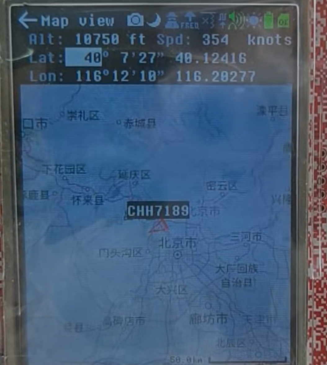
The list shows the ICAO address, flight number, latitude and longitude, altitude and speed of each aircraft, and selecting an entry opens its detail view. The test passes once real flights are listed with those fields displayed.
1090 MHz reception benefits strongly from antenna placement. A clear view of the sky, away from buildings and metal, changes the number of decoded aircraft far more than any gain adjustment does.
Firmware Versions and Upgrade Value
This chapter compares the firmware this manual is based on, v2.4.0, with the current release v2.4.0.2, and explains what the upgrade actually changes for the experiments in the previous chapters.
What Changed between v2.4.0 and v2.4.0.2
The difference is visible in the published files: the firmware archive grew from 8,414,251 bytes in v2.4.0 to 8,434,626 bytes in v2.4.0.2. Every procedure in this manual applies unchanged to both versions.
Application-level Advantages of v2.4.0.2
ADS-B reception is the experiment that benefits directly, since the official improvements in v2.4.0.2 specifically target ADS-B RX signal reception quality.
In practice this shows up as a higher decoding rate at 1090 MHz and more stable list entries: flights appear earlier and drop out less often. The wait between an entry first showing only its ICAO address and then displaying complete latitude, longitude and altitude is also generally shorter.
If ADS-B is a significant part of your use, v2.4.0.2 is worth the upgrade. If it is not, either version is fine.
Nightly builds carry the newest features and the newest bugs. For a device you rely on, stay on stable releases and keep a known-good firmware file on the SD card so that a bad flash can be reversed by Method 1 alone, without needing a computer.
Reference
https://github.com/OpenSourceSDRLab/mayhem-firmware/releases
https://github.com/portapack-mayhem/mayhem-firmware/releases
https://github.com/OpenSourceSDRLab
https://opensourcesdrlab.com/blog
https://www.reddit.com/r/OpenSourceSDRLab
https://opensourcesdrlab.com/products/hackrf-pro-h4m-pro
Follow our YouTube channel for more video tutorials: https://www.youtube.com/@OpenSourceSDRLab