1 Test Environment and Pass Criteria
Overall Pass Criteria: All three JTAG regions complete verification; the sdr0 interface appears after QSPI bootup; the TX FPGA counter and over-the-air loopback both meet threshold requirements; RX can identify at least one WiFi network with valid FCS checksum.
2 JTAG Programming Flow
2.1 Pre-Programming Check
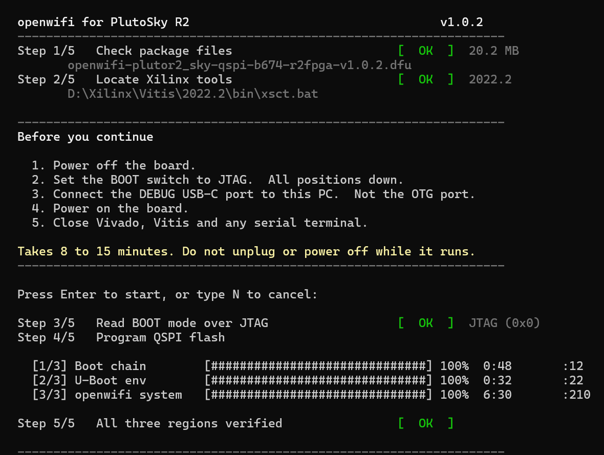
Power off the board, switch all BOOT dip switches down to enter JTAG boot mode.
Connect the PC via DEBUG USB‑C. Do NOT use OTG USB‑C for JTAG programming.
Power on the board. Close Vivado, Vitis, PuTTY, MobaXterm and other programs that may occupy the JTAG or serial port.
Ensure that boot.bin, fsbl.elf, openwifi-plutor2_sky-uboot-env.bin and the target system image in the jtag directory remain in the original directory structure.
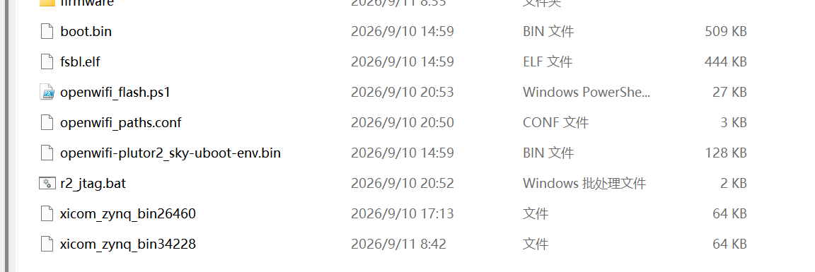
Double-click to run r2_jtag.bat. If the tool cannot be located automatically, configure the xsct path in jtag\openwifi_paths.conf.
2.2 Fixed Programming Sequence of Script
3 QSPI Boot and Wireless Initialization Verification
Power off the board after programming is completed.
Switch BOOT to QSPI mode: set switch No.1 to UP, and the rest to DOWN.
Power on the board again and wait about 30 seconds for Linux boot completion.
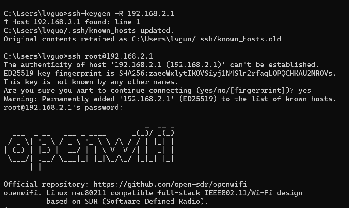
Log in via the DEBUG USB‑C serial port with parameters 115200 8N1. Username: root; Password: openwifi.
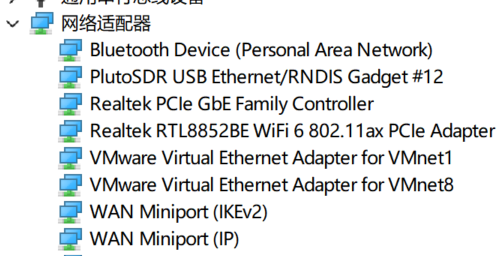
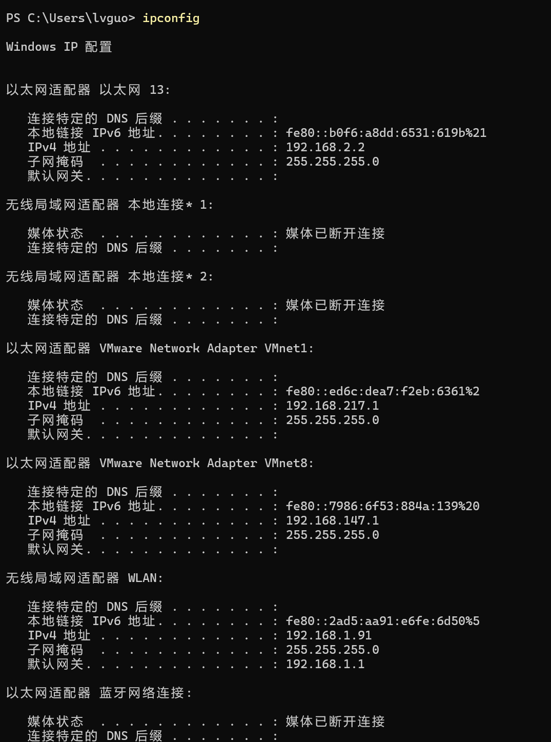
3.1 Board Connection Method
3.2 Verification Method
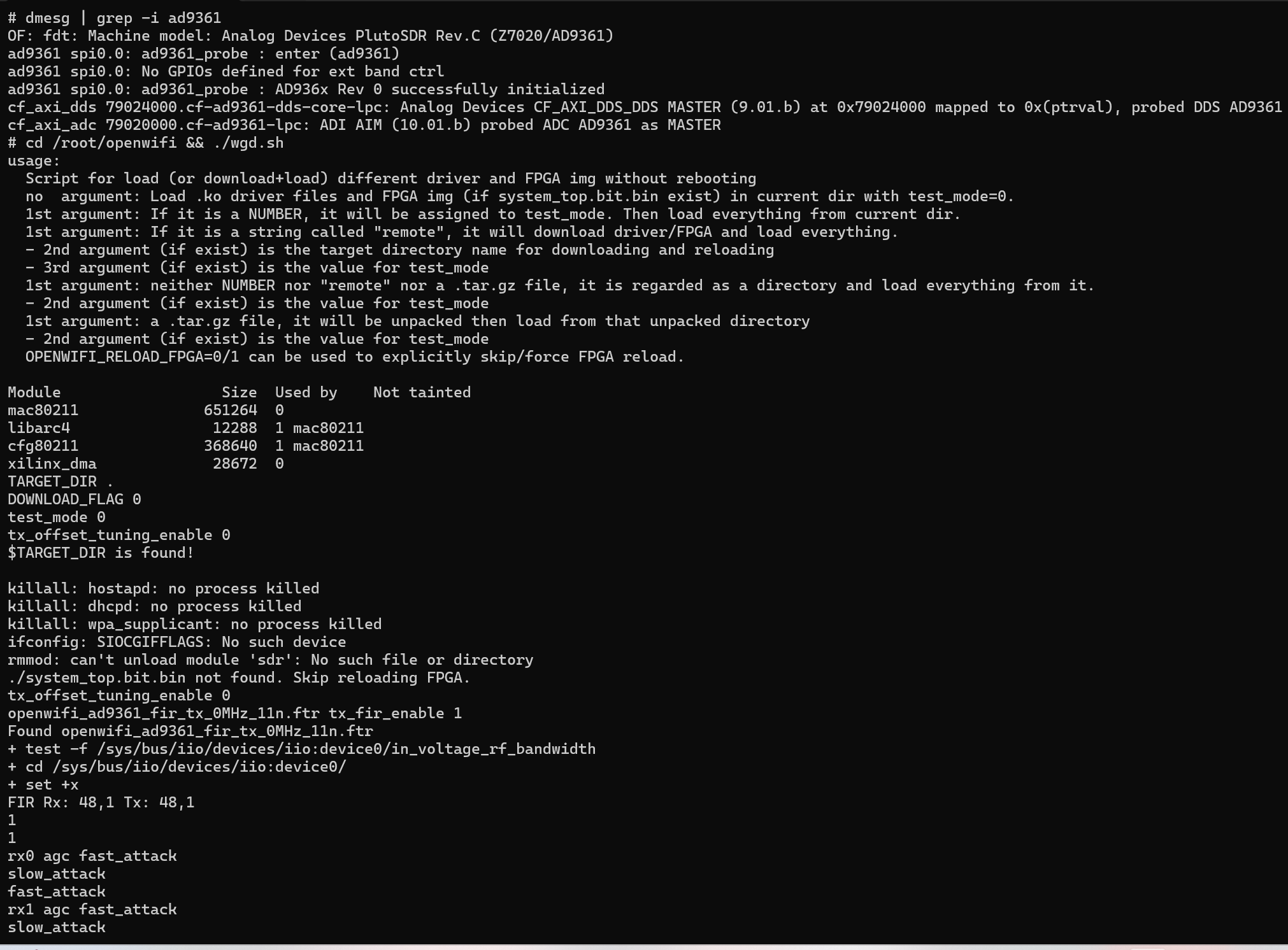
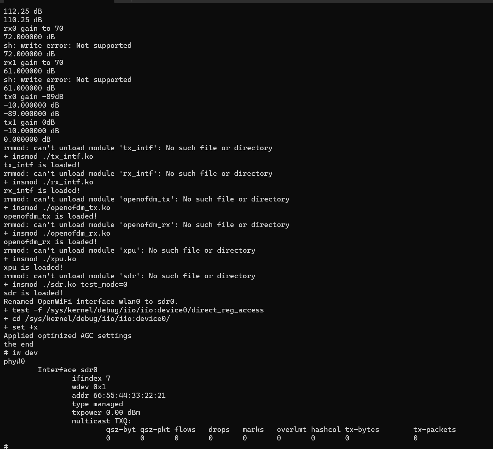
Run the following commands to check the RF driver and openwifi interface.
dmesg | grep -i ad9361
cd /root/openwifi && ./wgd.sh
iw dev
4 TX Transmission Function Verification
4.1 Method 1:
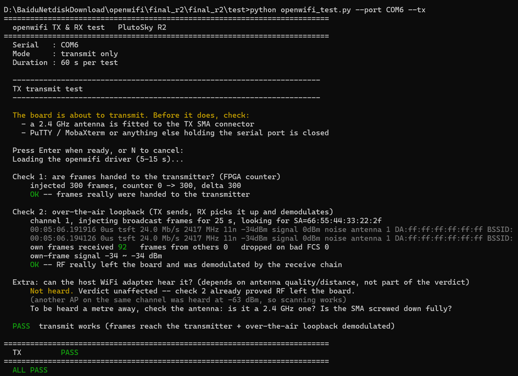
Close the terminals occupying the serial port (e.g., PUTTY). Confirm that TX1 is connected to the 2.4 GHz antenna. Navigate to the test directory and run the following commands.
4.2 Method 2:
Open PUTTY and enter the following commands:
cd /root/openwifi
./wgd.sh
ip link
ip link set sdr0 down; iw dev sdr0 set type monitor; ip link set sdr0 up; iw dev sdr0 set channel 11
./stat_enable.sh 1
S=/sys/devices/soc0/fpga-axi@0/fpga-axi@0:sdr
cat $S/tx_data_pkt_need_ack_num_total
Record this value.
MAC=$(cat /sys/class/net/sdr0/address | tr -d ":")
cd inject_80211 && ./inject_80211 -m g -r 4 -n 300 -s 300 -d 3000 -t d -e 0 -a 001122334455 -b $MAC sdr0
cat $S/tx_data_pkt_need_ack_num_total
cat $S/tx_data_pkt_need_ack_num_total_fail
cat $S/tx_data_pkt_mcs_realtime
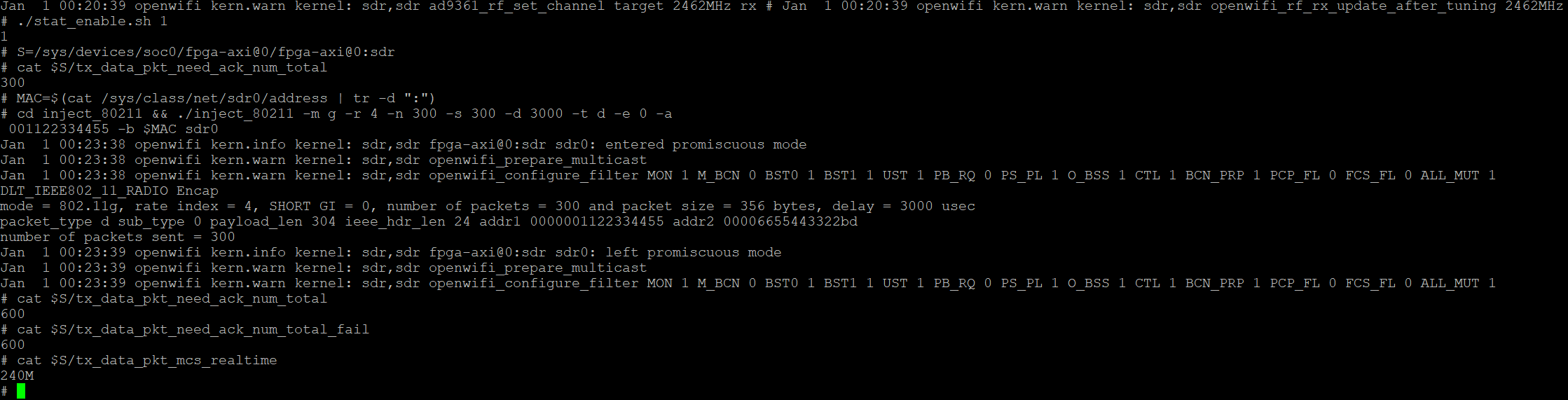
The inject_80211 program successfully transmits all 300 ACK-required data frames. The target MAC 001122334455 does not exist; no device returns ACK. All 300 packets time out, hence the fail count = 300. Packets are truly transmitted over the air, yet no ACK can be received, resulting in full timeout. The real-time MCS rate is 240M, and the RF link works normally.
5 RX Reception Function Verification
5.1 Method 1:
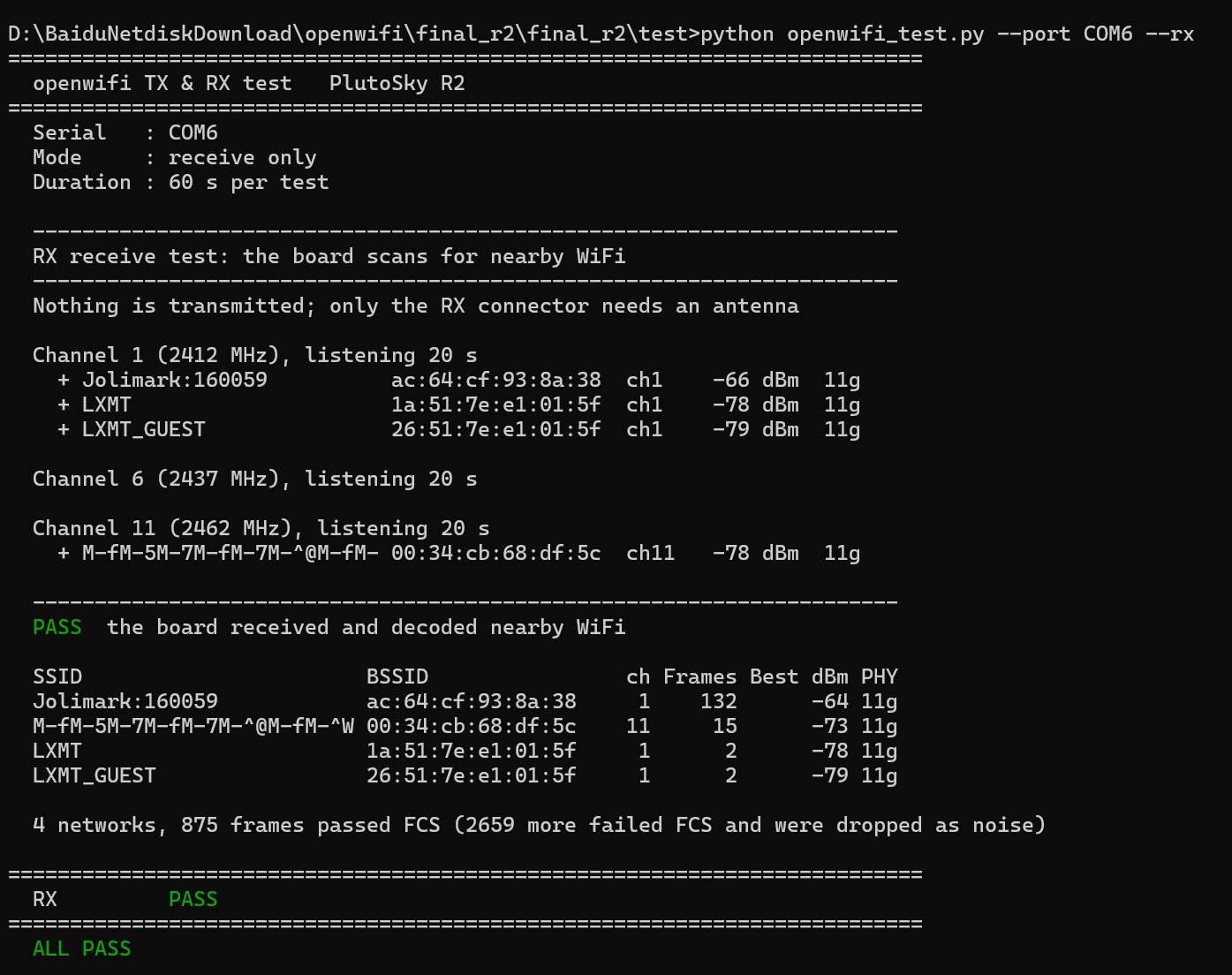
Confirm that RX1 is connected to the 2.4 GHz antenna. The script switches the board to monitor mode, and listens on channels 1, 6, 11 sequentially by default.
RX judgment only counts frames with passed FCS check. Bad-fcs frames are discarded as noise or demodulation failures. The test passes if at least one valid WiFi network with SSID/BSSID is detected.
5.2 Method 2:
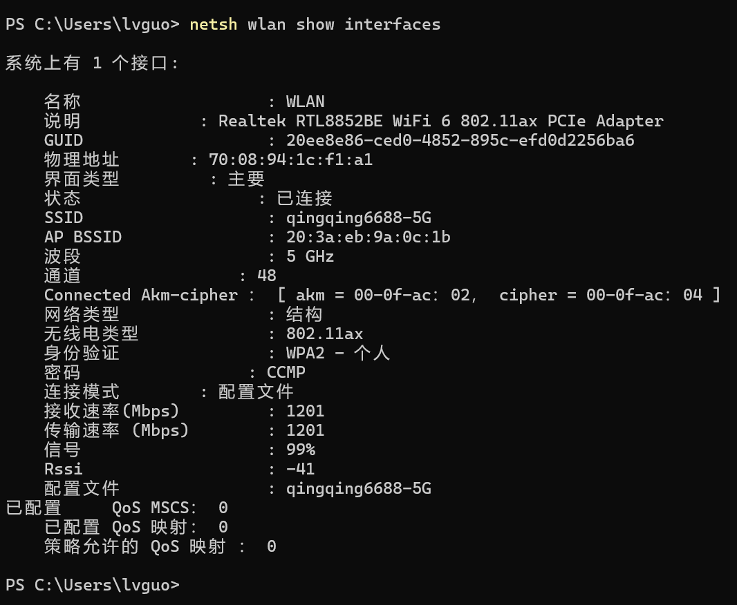
Enter the following in Windows PowerShell
netsh wlan show interfaces
Automatically read the current channel of your laptop. My channel is 48.
Open PuTTY → Serial → COM6 → Speed 115200 → Open, log in with root /openwifi. (If the # prompt appears directly, login is successful.)
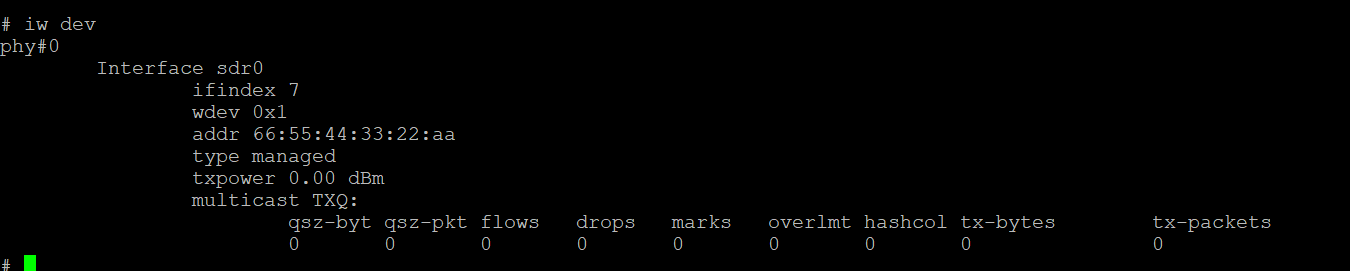
Enter iw dev
The test is OK if Interface sdr0 can be seen.
If not, enter: cd /root/openwifi && ./wgd.sh
Then enter:
cd /root/openwifi
ip link set sdr0 down; iw dev sdr0 set type monitor; ip link set sdr0 up; iw dev sdr0 set channel 48
./set_rx_monitor_all.sh 1
./agc_settings.sh 1
tcpdump -i sdr0 -e -nn -c 60
The test succeeds if the following command output is displayed.

If the set number of WiFi packets are captured and no packet loss occurs in the system kernel, it indicates that the SDR monitoring and receiving link works properly and the over‑the‑air WiFi signals are successfully received.
6 Real Over-the-Air AP/STA Test with two R2 boards:
6.1 Preparations
Both boards are flashed with openwifi firmware. BOOT dip switches are set to QSPI mode, and Linux boots normally after power-on.
The DEBUG USB‑C ports of both boards are connected to the PC. Confirm corresponding COM ports appear in Windows Device Manager.
Open one serial console window for each board with parameters 115200 8N1. Login credential: user root, password openwifi.
Confirm test\openwifi_test.py is NOT running. It occupies the serial port and leaves the board in monitor mode.
Place the two boards 30 cm ~ 1 m apart. On each single board, mount TX and RX antennas orthogonally as much as possible.
Note: Antennas shall be connected to TX1 and RX1 on each board. A total of four 2.4 GHz antennas are required for the two boards. Tighten all SMA connectors fully.
6.2 Operation Procedure
Step 1 Load OpenWiFi Driver [Board A + Board B]
Execute on the serial console of both boards. This step reloads the FPGA bitstream and inserts kernel modules, taking approximately 15 seconds.
cd /root/openwifi
./wgd.sh
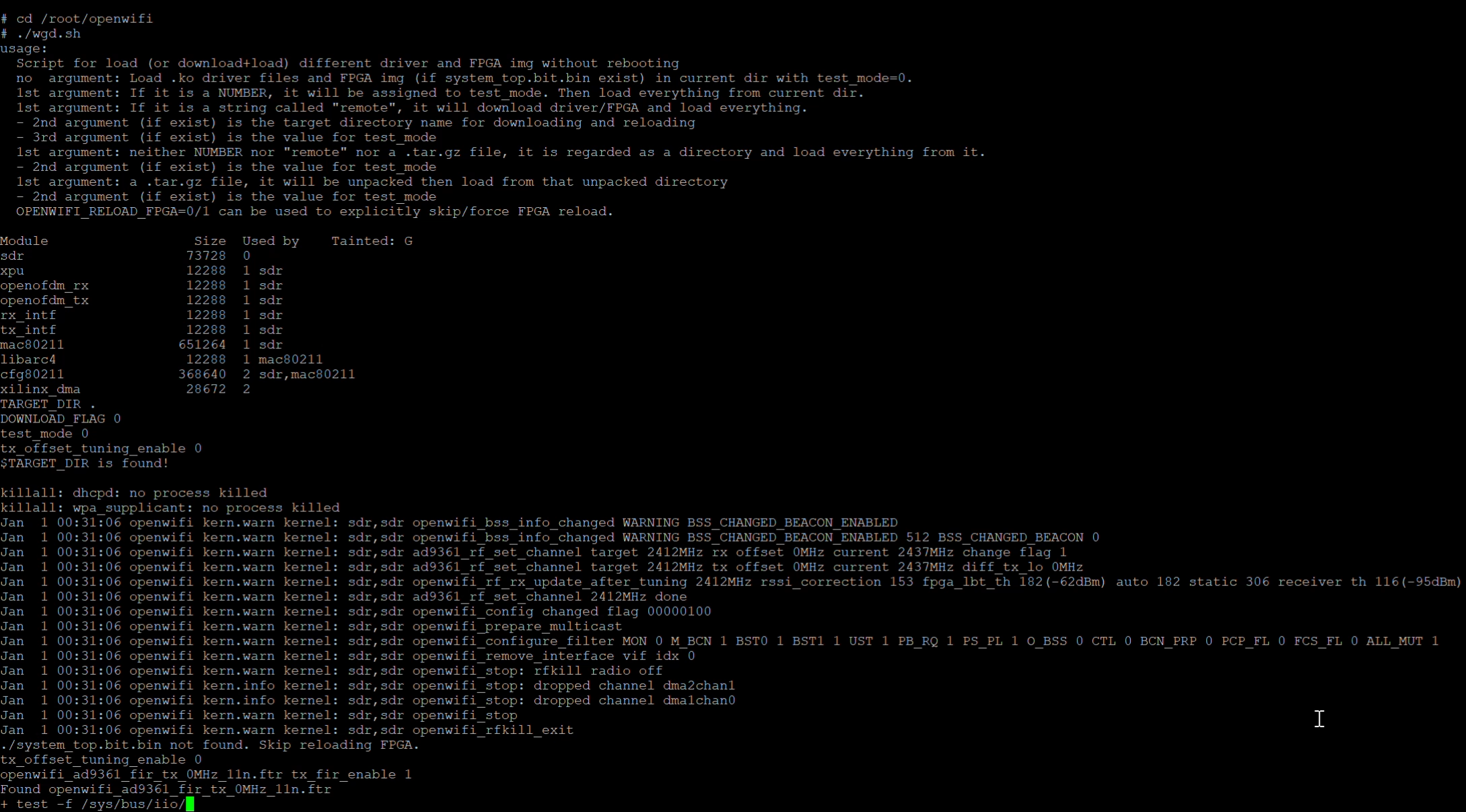
Run ip link show sdr0. Pass if interface sdr0 appears. If not, re-run ./wgd.sh.
Log entries Renamed OpenWiFi interface wlan0 to sdr0 and Applied optimized AGC settings indicate normal completion. The message rmmod: can't unload module 'sdr' can be ignored; it occurs when no old module exists to unload on first load.
Step 2 Bring up interface, scan and select channel [Board A・AP]
Scanning requires the interface to be UP. The interface remains down after wgd.sh completes and must be brought up first.
ip link show sdr0
ip link set sdr0 up
iw dev sdr0 scan | grep -e SSID -e freq
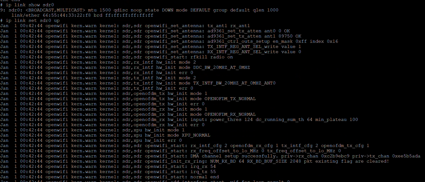
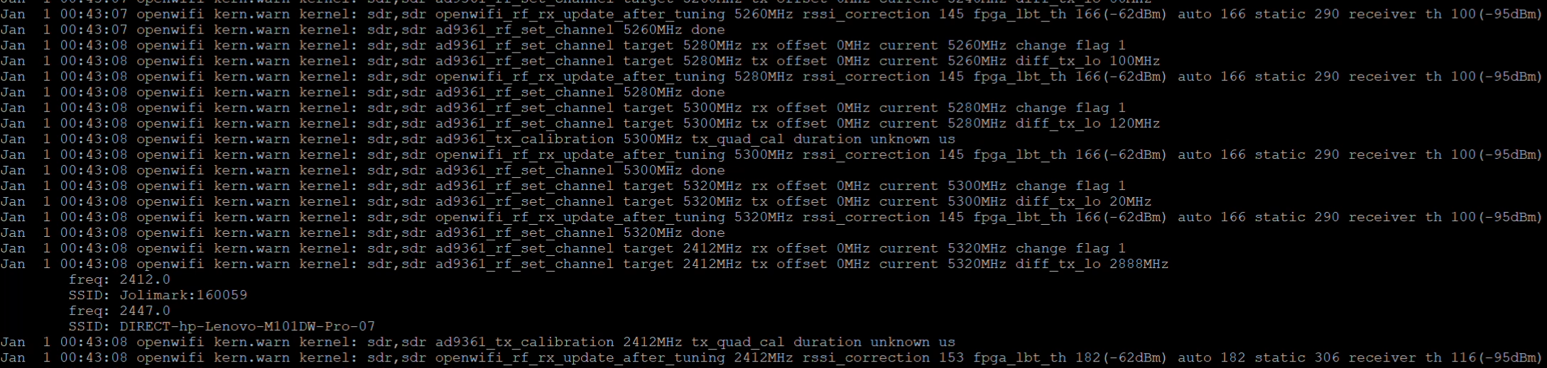
Determine channel occupancy by frequency: 2412 for channel 1, 2437 for channel 6, 2462 for channel 11. Select a free channel. This procedure uses channel 6 for demonstration. If another channel is selected, update all channel=6 entries accordingly.
Step 3 Write 2.4 GHz hostapd configuration [Board A・AP]
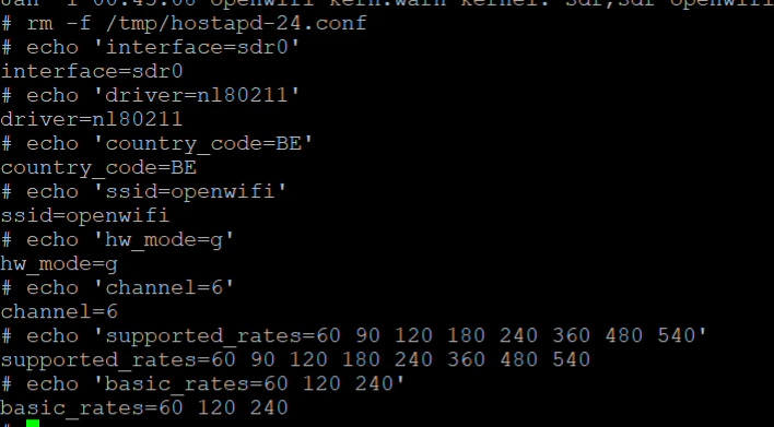
Append line by line. Pasting large blocks over 115200 serial may cause character loss; multiple echo commands are more reliable.
rm -f /tmp/hostapd-24.conf
echo 'interface=sdr0' >> /tmp/hostapd-24.conf
echo 'driver=nl80211' >> /tmp/hostapd-24.conf
echo 'country_code=BE' >> /tmp/hostapd-24.conf
echo 'ssid=openwifi' >> /tmp/hostapd-24.conf
echo 'hw_mode=g' >> /tmp/hostapd-24.conf
echo 'channel=6' >> /tmp/hostapd-24.conf
echo 'supported_rates=60 90 120 180 240 360 480 540' >> /tmp/hostapd-24.conf
echo 'basic_rates=60 120 240'
Step 4 Start AP [Board A・AP]
Hostapd needs to take over the interface. Bring the interface down, switch to managed mode then bring it up. agc_settings.sh must run after hostapd, as hostapd restarts the radio chain.
cd /root/openwifi
killall hostapd 2>/dev/null
ip link set sdr0 down
iw dev sdr0 set type managed
ip link set sdr0 up
hostapd -B /tmp/hostapd-24.conf
./agc_settings.sh 1
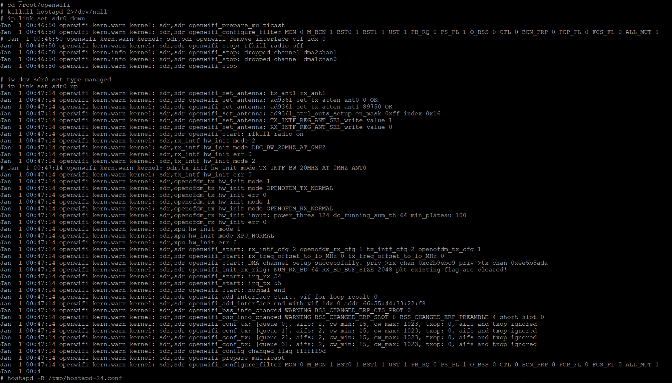
The sequence openwifi_remove_interface → openwifi_stop → openwifi_start → add_interface is normal when hostapd claims the interface. rfkill: Cannot open RFKILL control device occurs because this buildroot image lacks /dev/rfkill; it does not affect functionality.
Step 5 Verify AP status and configure IP address [Board A・AP]
Hostapd -B runs in background and does not print immediate success/failure. A common failure symptom is hostapd exiting several seconds after launch. This step cannot be skipped.
ps | grep '[h]ostapd'
iw dev sdr0 info
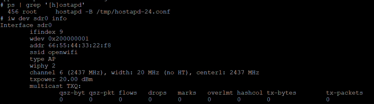
Configure IP after verification. Keep this console open to print client association logs:
ifconfig sdr0 192.168.13.1
Step 6 Switch Board B to client mode [Board B・Client]
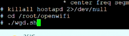
The killall hostapd command is critical. If Board B was previously broadcasting an AP (such as openwifi-r2 seen in Step3), it cannot associate as a client unless hostapd is terminated.
killall hostapd 2>/dev/null
cd /root/openwifi
./wgd.sh
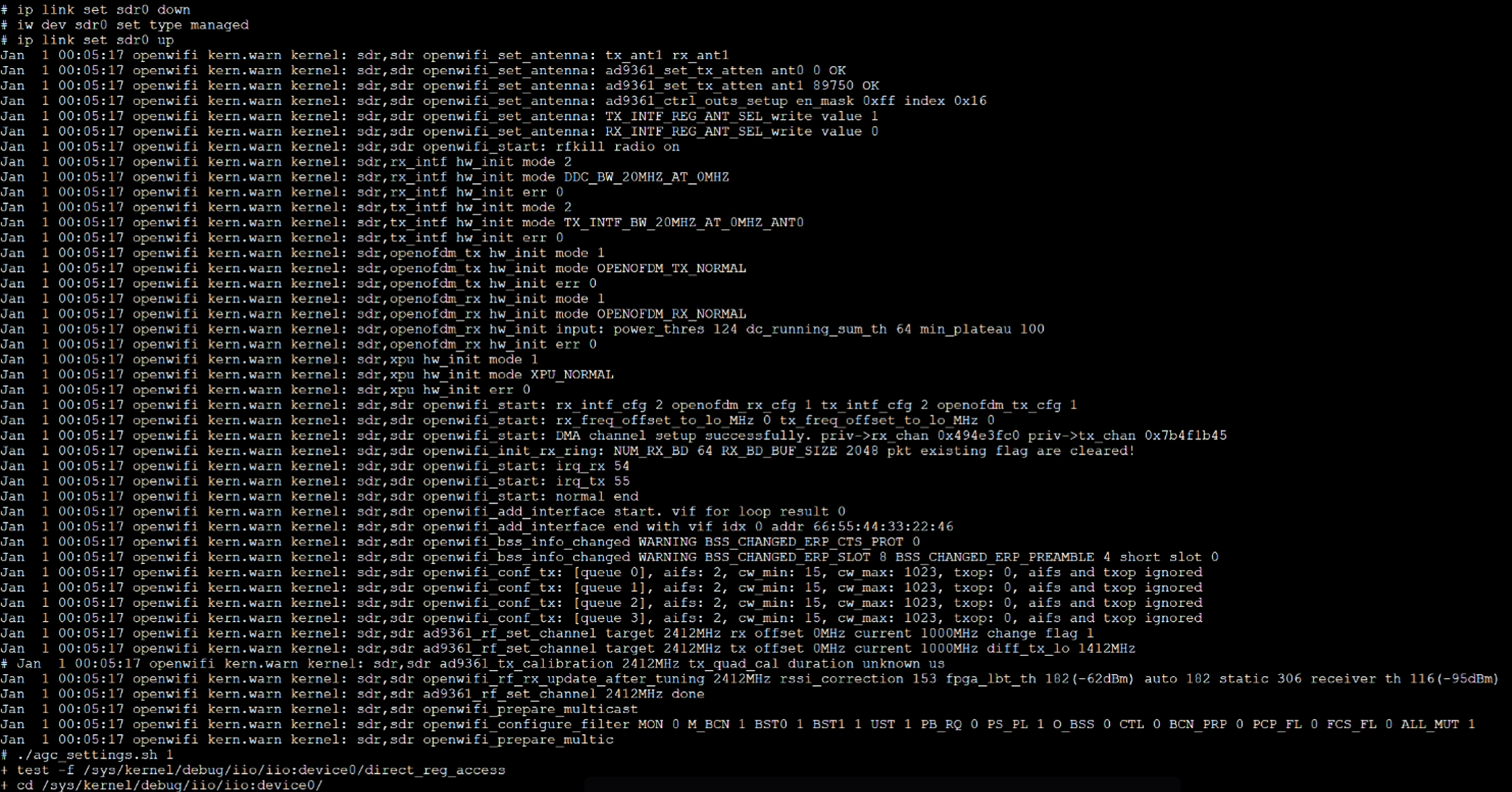
ip link set sdr0 down
iw dev sdr0 set type managed
ip link set sdr0 up
./agc_settings.sh 1
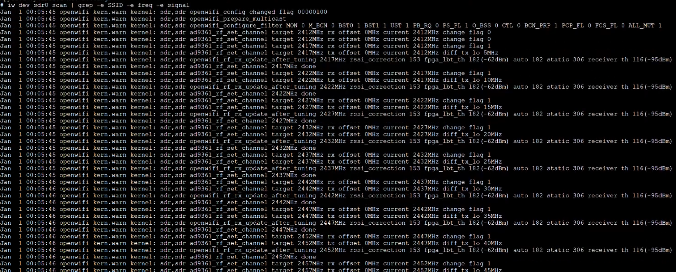
Step 7 Verify Board A AP is detectable by scan [Board B · Client]
iw dev sdr0 scan | grep -e SSID -e freq -e signal
Step 8 Association [Board B・Client]
Use iw for direct association for open networks; wpa_supplicant is not required.
iw dev sdr0 connect openwifi
sleep 3
iw dev sdr0 link
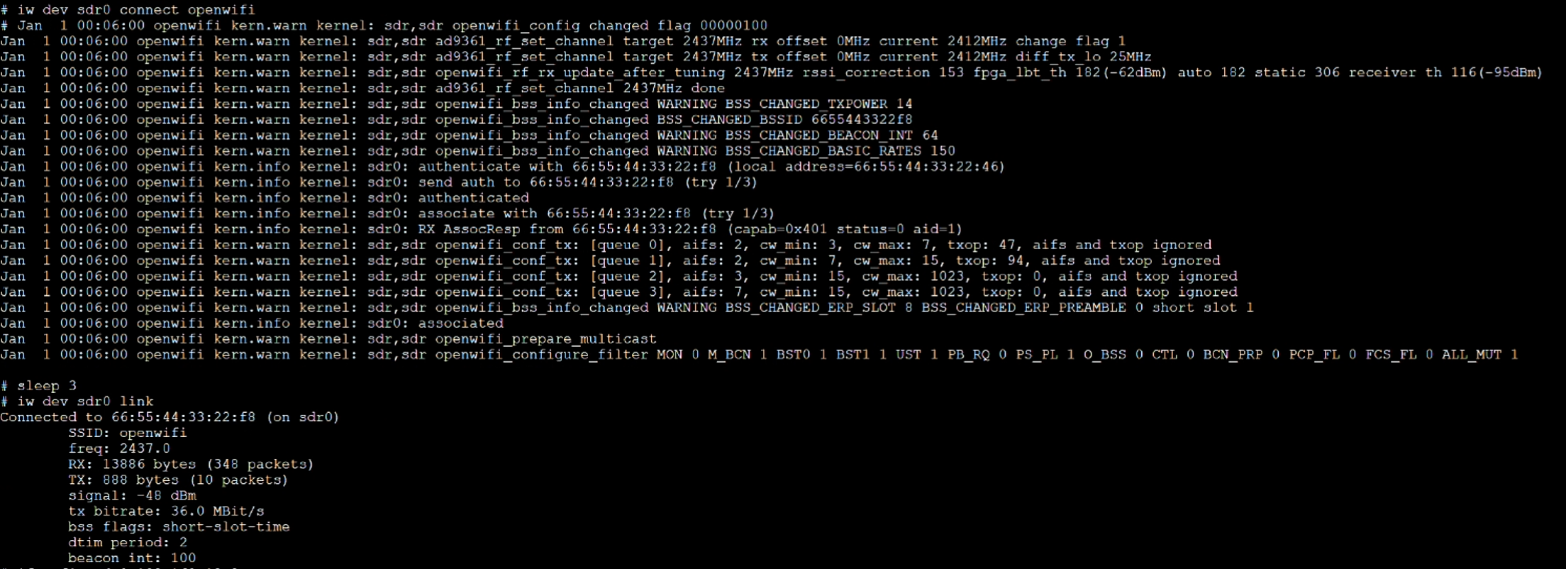
Board B output shall show Connected to 66:55:44:33:22:9e (on sdr0) and SSID: openwifi (MAC belongs to Board A).
Step 8 Configure IP and verify connectivity [Board B · Client]
ifconfig sdr0 192.168.13.2
ping -c 5 192.168.13.1

Packet loss of 0 to 2% and latency ranging from several milliseconds to tens of milliseconds are considered normal.