This guide walks through the complete deployment of the PlutoSky R2 running Tezuka firmware: hardware and software preparation, SD‑card firmware deployment, three boot modes and DIP‑switch operation, IIO context verification, config.txt parameter configuration, web dashboard activation, the built‑in Maia‑SDR waterfall, and brick recovery via Flash erasure and DFU programming, along with full hands‑on demonstrations.
YouTube Video Link: https://www.youtube.com/watch?v=c4ZYFDh0o9Y
Overview
We elaborate from eight perspectives.
• Device Preparation
• Three Boot Modes and DIP Switch Definition
• Factory Firmware Backup
• SD Card Firmware Deployment and Boot Verification
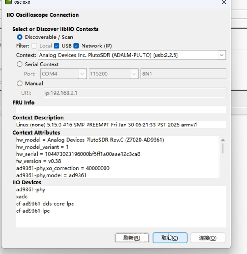
• First Connection and IIO Context Verification
• config.txt Parameter Configuration and Web Dashboard Activation
• Built-in Maia-SDR Waterfall and RF Path Verification
• Brick Recovery: Flash Erasure and DFU Programming
Chapter 1 Device Preparation
Covers the hardware and software checklist, and the firmware download and package structure, the foundation for later flashing and experiments.
Red line: Under no circumstances shall you flash QSPI Flash via the .frm method; this will brick the device. The R2 is equipped with an SD‑card slot — always use the SD‑card boot method.
1.1 Hardware Checklist
1.2 Software Checklist (Windows)
1.3 Firmware Download and Package Structure
Step 1 Download the correct asset
Go to https://github.com/F5OEO/tezuka_fw/releases and download only tezuka-plutoskyr2-*.zip.
Step 2 Identify the two folders
After extraction the package contains exactly two folders:
• sdimg/ — for SD card boot. This is the one you use.
• flash/ — for QSPI programming. Do not touch.
Chapter 2 Three Boot Modes and DIP Switch Definition
The R2 carries two complete firmware sets simultaneously, and which one runs is decided purely by hardware before any software executes.
2.1 DIP Switch Boot Mode Table
The R2 carries a DIP switch block that must only be operated with the device powered off. Settings changed while powered are ignored, because the Zynq BootROM samples these pins once at power-on.
2.2 The Dual Firmware Architecture
An R2 normally ships with both firmware sets present: Tezuka pre-installed on the SD card, and the modified stock PlutoSDR firmware in the QSPI Flash.
Chapter 3 Factory Firmware Backup
Before any file is written to the SD card, both factory firmware sets must be archived.
3.1 Back Up the Factory SD Card
Step 1 Copy the entire card
Copy the full contents of the factory SD card to a computer and archive it. Do this before formatting, not after.
Step 2 Confirm against the official backup
The official backup location for the factory SD card firmware is the repository OpenSourceSDRLab/PlutoSky-R2, under firmware/SD card firmware/. It contains five files:
• BOOT.bin
• devicetree.dtb
• uEnv.txt
• uImage
• uramdisk.image.gz
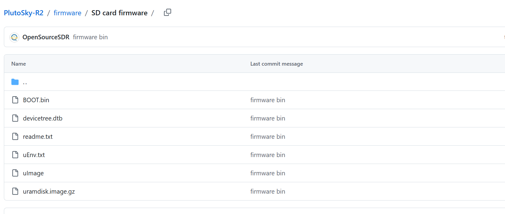
All five must be present. A backup missing any one of them will not boot.
3.2 Back Up the Factory Flash Firmware
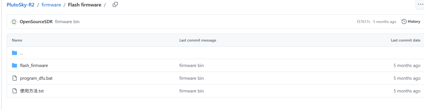
The factory Flash firmware lives in the same repository under firmware/Flash firmware/, and contains program_dfu.bat.
Chapter 4 SD Card Firmware Deployment and Boot Verification
The actual Tezuka installation, which takes roughly five minutes, plus the standard boot self-test criteria for judging a successful deployment.
4.1 SD Card Deployment Steps
Step 1 Format the card
Format the microSD card as FAT32. Cards larger than 32GB require a third-party tool to force FAT32.
Step 2 Copy the firmware contents
Extract the firmware zip, enter the sdimg/ folder, select everything inside the folder, and copy it to the root directory of the SD card.
Step 3 Set the boot mode
With the device powered off, set the DIP switch to SD Card Boot mode (Switch 1 VCC3V3, Switch 2 VCC3V3).
Step 4 Connect and power on
Insert the SD card and connect the USB-C ports, then apply power. Connect both ports — one to the USB data port, one to the Type-C DEBUG composite port. Powering from a single port provides insufficient current and causes repeated reboots.
Step 5 Wait for boot
Allow approximately 20 to 30 seconds for the boot to complete.
4.2 Boot Self-test Criteria
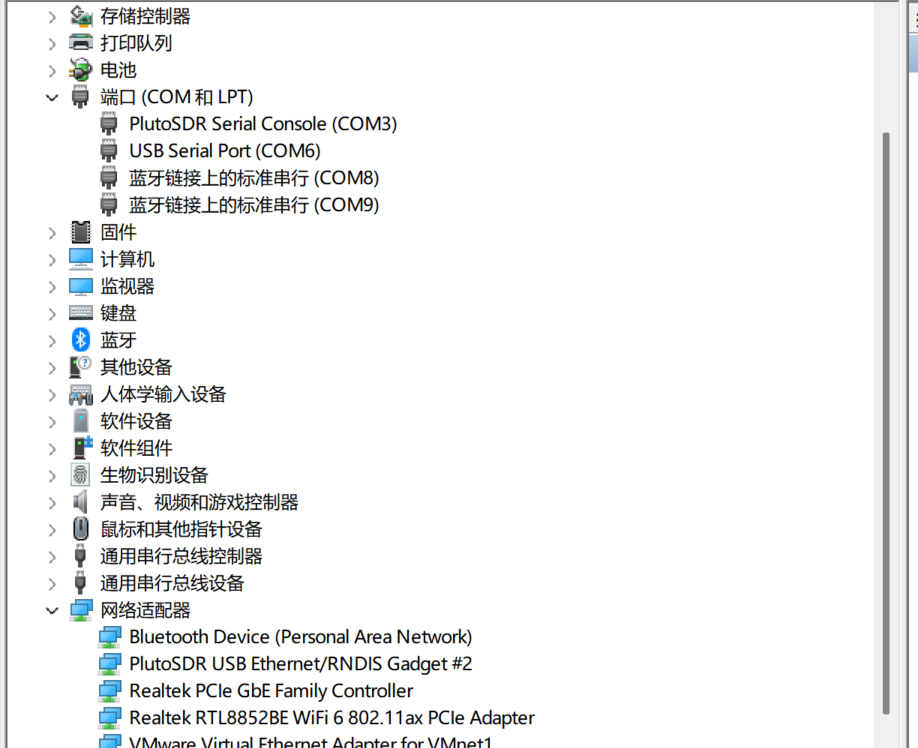
Normal boot criteria:
• A removable drive (virtual mass storage) appears on the computer, containing config.txt
• A new adapter named PlutoSDR USB Ethernet/RNDIS Gadget appears in the network adapter list
Chapter 5 First Connection and IIO Context Verification
The fastest objective proof that the firmware is alive and the RF front end is enumerated correctly, using the libiio command-line tools.
5.1 Command Line Verification
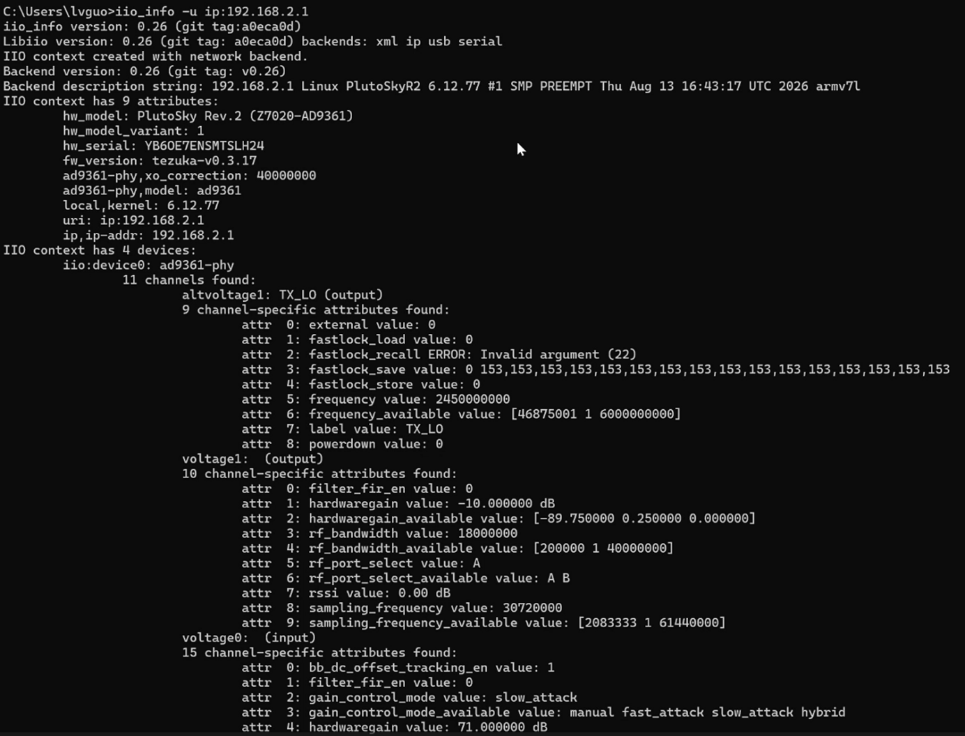
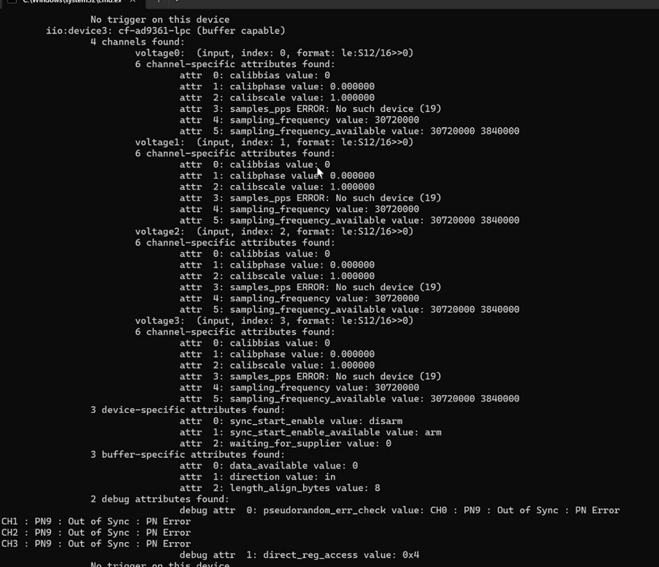
Step 1 Confirm the IIO context
Run the following, where the default device IP under SD card boot is 192.168.2.1:
iio_info -u ip:192.168.2.1
Step 2 Log into the device
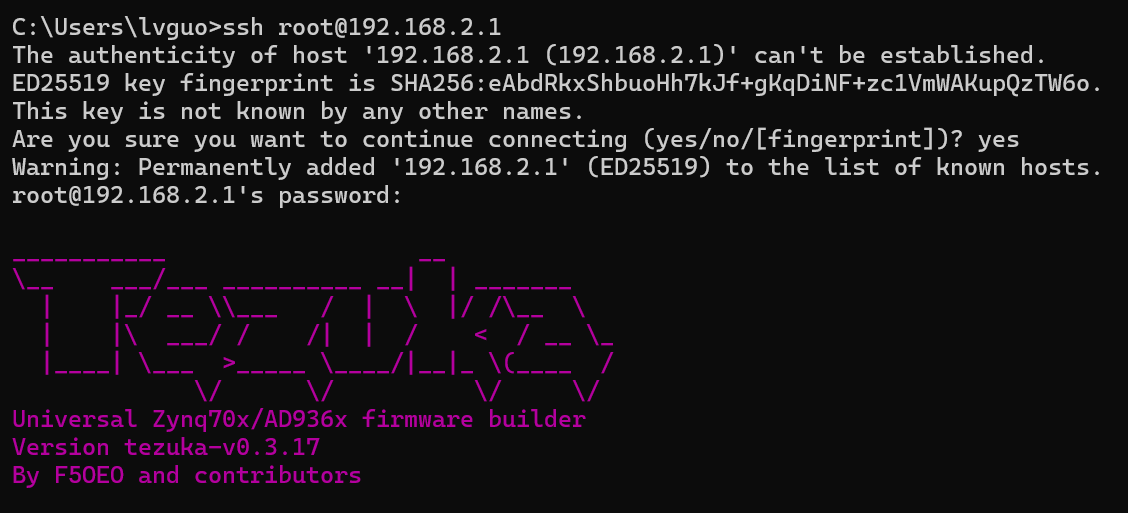
SSH into the device using username root and password analog:
ssh root@192.168.2.1
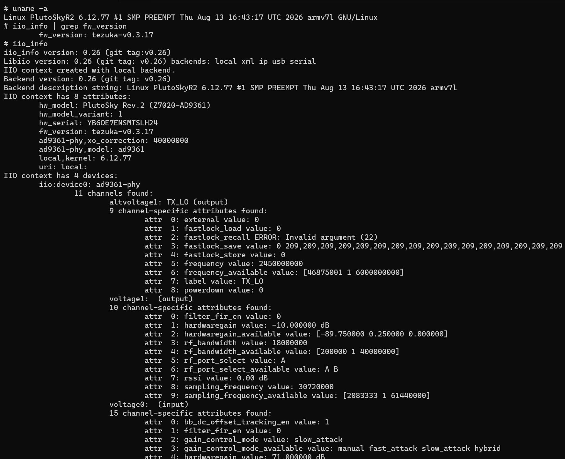
Run the following commands in sequence:
uname -a
iio_info | grep fw_version
iio_info
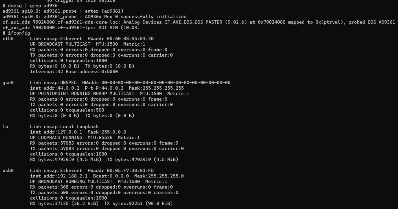
dmesg | grep ad936
ifconfig
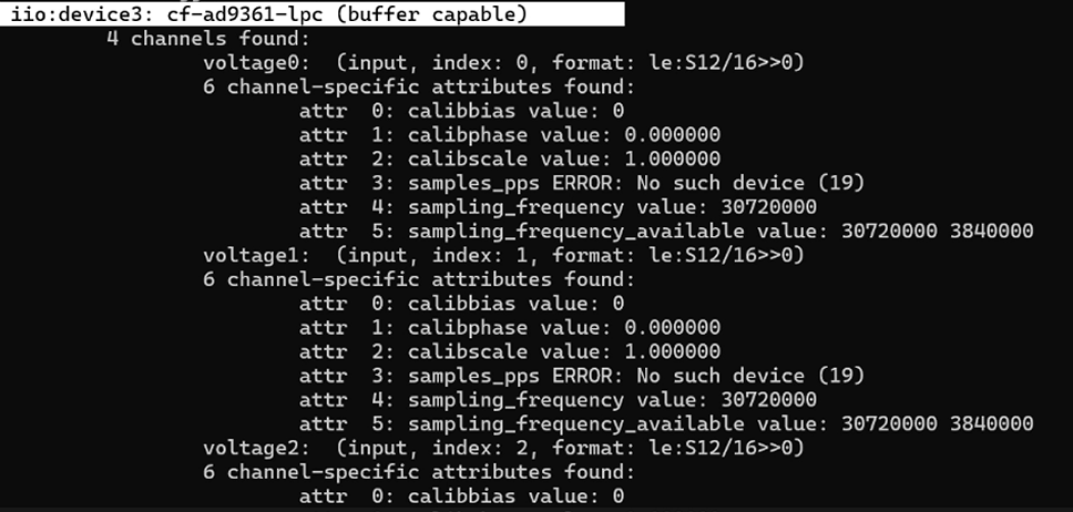
The following verifications can be completed: The SD card firmware boots normally and the Linux operating system runs properly; Retrieve the current firmware version of the device (tezuka-v0.3.17); Confirm that the AD9361 RF hardware driver is loaded and the device is recognized successfully; Check the network IP configuration to ensure the host PC can establish communication with the device via the SSH / IIO protocol
5.2 The Four Expected IIO Devices
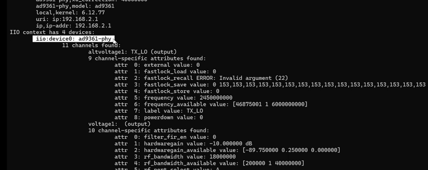
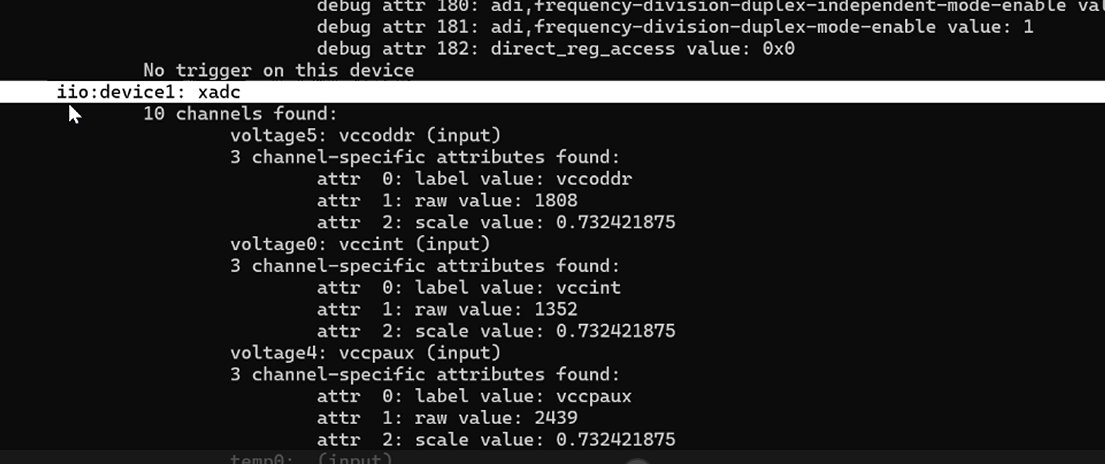
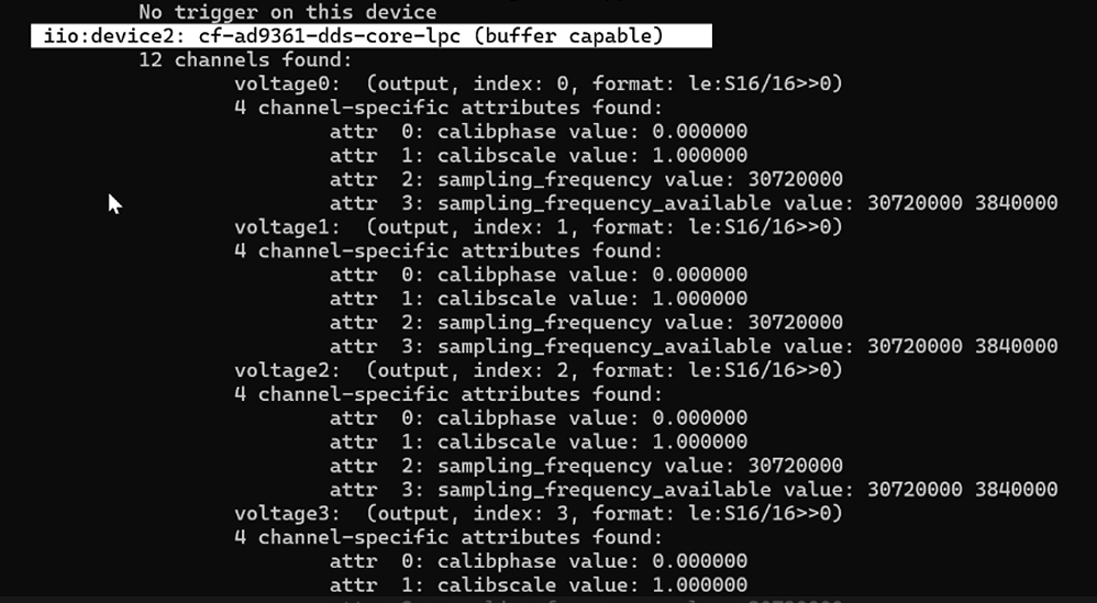
The iio_info output must list the following four devices with no errors reported.
If any of the first three is missing, the FPGA bitstream did not load and the deployment must be repeated. The xadc device is a system monitor only and has no bearing on RF operation.
Chapter 6 config.txt Parameter Configuration and Web Dashboard Activation
6.1 Baseline Edits
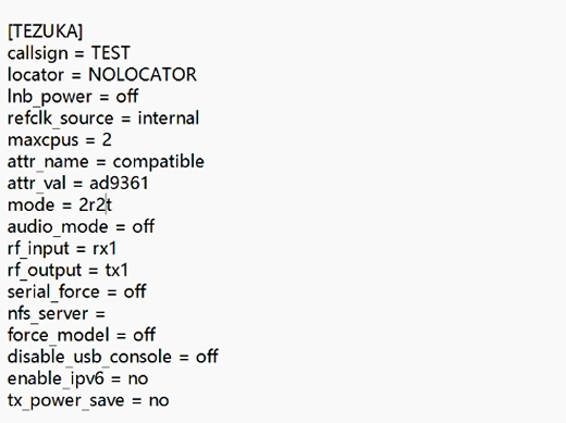
Open config.txt on the TEZUKA drive and make the two baseline changes:
Change callsign = NOCALL to callsign = TEST
Change mode = 1r1t to mode = 2r2t
6.2 Parameter Reference Table
Adjust the remaining parameters according to your own configuration.
6.3 The Save Procedure
Step 1 Save and eject
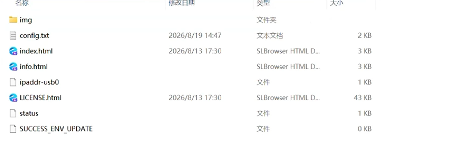
After editing the parameters, click save, then eject the device properly — this is not the same as simply unplugging it.
Step 2 Wait for re-enumeration
Wait three seconds. The device disappears and reappears. A file named SUCCESS_ENV_UPDATE appearing on the drive confirms the parameters were written successfully.
Step 3 Power cycle
Disconnect the device power, wait three seconds, and reapply power.
6.4 Web Dashboard Activation
Open a browser and navigate to http://192.168.2.1/index.html
The expected first-run behaviour, frequently mistaken for a fault: the page shows only an "Operator / Station identity" form, the Identity card on the right reads SWL-Anonymous.
This is not a bug. The dashboard is gated behind a configured callsign.
Step 1 Enter a callsign
Fill the Callsign field with your callsign, for example TEST. Operator name and Grid locator may be left blank.
Step 2 Save
Click Save changes. The button briefly changes to "Saved" and a yellow notice appears below reading "Callsign changed — reboot the device for it to take effect".
Step 3 Reboot
Reboot the device
Step 4 Hard refresh
Press the refresh button in the browser.
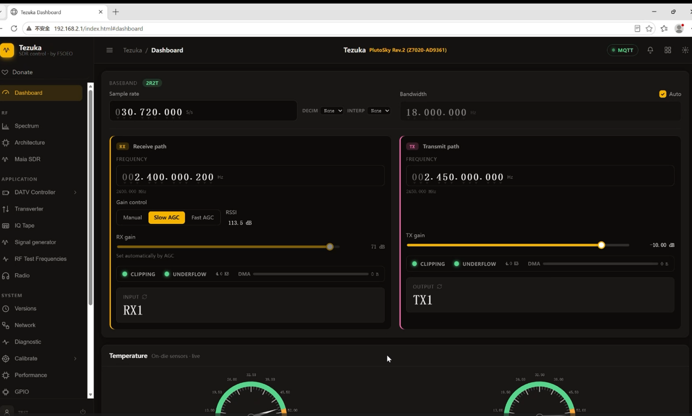
6.5 Dashboard Normal-state Criteria
The dashboard is correctly activated when all of the following are true simultaneously.
Once activated, the Tezuka dashboard reports device model, serial number, FPGA version, firmware build version, kernel version, U-Boot version, root filesystem, hostname, USB IP and MAC address, and the Ethernet MAC address.
Chapter 7 Built-in Maia-SDR Waterfall and RF Path Verification
The fastest possible go/no-go test of the receive path, requiring no host software at all.
7.1 Open the Waterfall
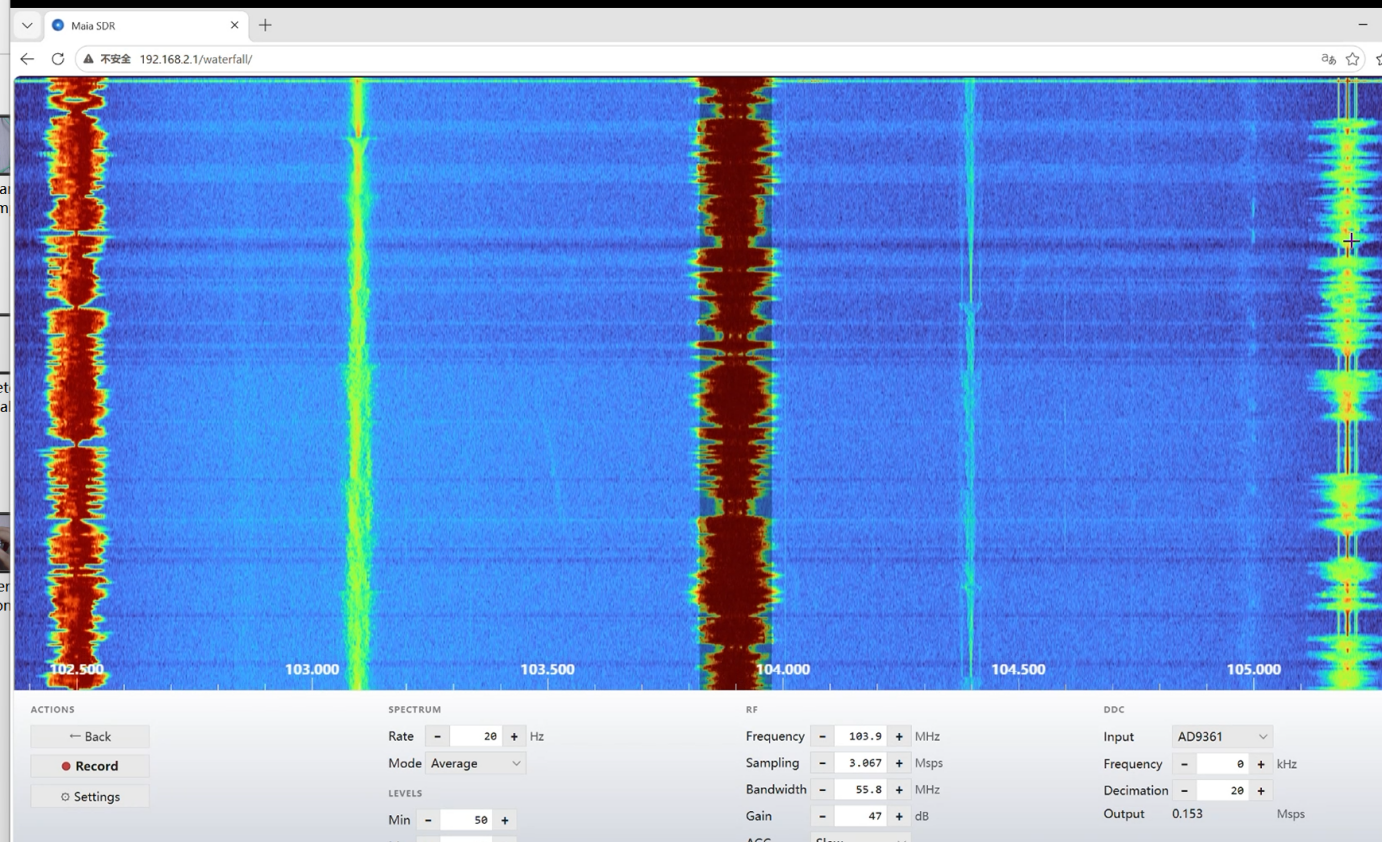
Navigate to http://192.168.2.1/waterfall/
This is the Maia-SDR instance integrated into the firmware. Because it needs no host application installed, it is the quickest way to establish whether the receive path works, and it should be the first test performed on any unit reported as faulty.
7.2 Interpretation
A live, moving waterfall with a visible noise floor confirms that the FPGA bitstream loaded, the AD9361 is configured, and the receive data path is streaming.
Chapter 8 Brick Recovery and Rollback
Two recovery scenarios and the exact procedures for each.
8.1 Case A: Tezuka Will Not Boot
Remove power, replace the SD card contents with the factory files archived in Chapter 3, and reapply power. That is the entire procedure.
The core value of SD card boot: no matter what goes wrong with Tezuka, the factory firmware in the QSPI Flash remains intact, so the device can never be genuinely bricked.
Two practical notes before reaching for the factory files. First, if the unit was working and is now not, substitute a second known-good SD card before anything else, since counterfeit cards are the leading cause of boot failure. Secondly, after restoring the device using the factory SD firmware, the unit will operate in the modified stock PlutoSDR mode. When accessing http://192.168.2.1/index.html, the Tezuka dashboard and waterfall page will no longer be available. This absence is expected and shall not be regarded as evidence of a failed restore.
8.2 Case B: Bricked due to incorrect Flash flashing
Bricking only occurs when Tezuka is written into the QSPI Flash via the .frm method.
The recovery principle is not to repair the damaged Flash contents. It is to boot a healthy U-Boot from the SD card, use it to erase the QSPI, and then reprogram the factory firmware over DFU.
8.3 Prerequisites
The entire recovery process consists of three parts: Flash erasure operation, JTAG firmware programming, and DFU firmware programming. Flash erasure is the prerequisite and basic step for all recovery procedures, which is used to clear the damaged firmware on the device. Under normal circumstances, the factory firmware can be flashed and the device repaired through DFU mode after erasure. If the computer fails to recognize the DFU device and the DFU programming process cannot be performed after Flash erasure, the JTAG firmware programming method can be adopted as a fallback solution. JTAG programming and DFU programming are two independent alternative solutions, and there is no need or possibility to execute both processes simultaneously.
8.4 Flash Erasure Procedure
Step 1 Boot from SD and open a serial session
With the device powered off, set the DIP to SD Card Boot, insert the SD card, connect the Type-C cable to the DEBUG port, and apply power.
Confirm the indicators before continuing: the LED indicator flashes continuously, and the DONE and PWR indicators are steadily on. If they are not, recheck the SD card seating, the DIP setting and the USB connection before going further.
Open Device Manager, find the USB COM Port and note its number. Launch PuTTY, set Connection Type to Serial, enter the COM port, set Speed to 115200, and click Open.
Step 2 Enter U-Boot
Press the RST button on the device. The LED indicator stops flashing immediately. Then press Enter on the keyboard and wait three to five seconds. The prompt Pluto> appearing in the terminal confirms U-Boot has been reached.
Step 3 Erase
At the Pluto> prompt, enter each command in sequence, pressing Enter after each:
sf probe
sf erase 0x0 0x2000000
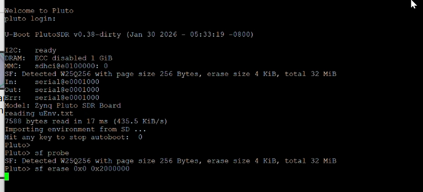
sf probe initialises the SPI Flash subsystem and probes the chip, printing its model, page size, erase sector size and total capacity. Read that output: the total should be 16 MiB. sf erase then erases 0x1000000 bytes, which is 16,777,216 bytes, from offset zero — on this 16 MB W25Q128 that is a full-chip erase. Note that the second argument is a length, not an end address.
The erasure takes approximately two to three minutes, and the terminal will appear frozen throughout. This is normal. Do not remove power and do not disconnect the USB cable during erasure, or the device may be genuinely damaged. An OK message indicates completion.
8.5 Flash Firmware via VIVADO in JTAG Mode
Applicable scenario: After Flash erasure is completed, if the computer cannot recognize the USB download gadget and the DFU procedure is unavailable, use this fallback solution to restore the device.
Step 1 Switch to JTAG boot mode
Power on the device in JTAG boot mode by switching the BOOT selector to JTAG when the device is powered off.
Step 2 Hardware Connection and Power‑up
Connect the DEBUG port of PlutoSky R2 to your computer with a Type-C data cable.Power on the device; the PWR indicator will light up red.
Step 3 Vivado Hardware Connection Operation
Launch the Vivado software → Click Open Hardware Manager → Wait for loading → Click Open target →Click Auto Connect→ Select and right-click XC7z020_1
Step 4 Solutions for Vivado Failing to Recognize Hardware Devices
If Vivado fails to detect the device: Navigate to .../nt64/digilent, run install_digilent.exe as Administrator, follow the wizard to install the driver, restart your computer, then reopen Vivado.
https://blog.csdn.net/weiweiliulu/article/details/106576366
Step 5 Configuration Memory and Programming Files
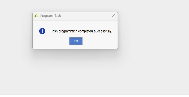
Once the device (e.g., xc7z020_1) is detected: Right-click and select Add Configuration Memory Device → Search for w25q128, select the x4 version and confirm → Import the provided boot.bin and fsbl.elf files → Set Address Range to the entire Flash → Check the 4 configuration options → Click Apply and wait 3-5 minutes for programming.
Flash programming success.
Close Program
8.6 DFU Programming Procedure
Applicable scenario: After Flash erasure is completed, if the computer can normally recognize the USB download gadget, this standard recovery solution is preferred.
Step 1 Switch to Flash boot mode
Power off the device, set the DIP to Flash boot mode, remove the SD card to eliminate any ambiguity about the boot source, connect the USB port to the computer with a data cable, and power on.
Step 2 Verify DFU entry
Open Device Manager. USB download gadget appearing under "Universal Serial Bus devices" confirms the device is in DFU mode and ready to be programmed.
If it does not appear, the Flash was not fully erased or the ADI driver is not installed. Recognising this device means only that programming can begin — it is not a sign that recovery is complete.
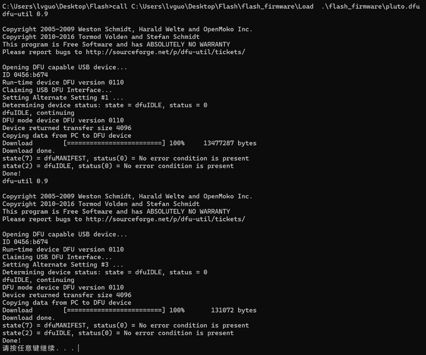
Step 3 Correct the script paths
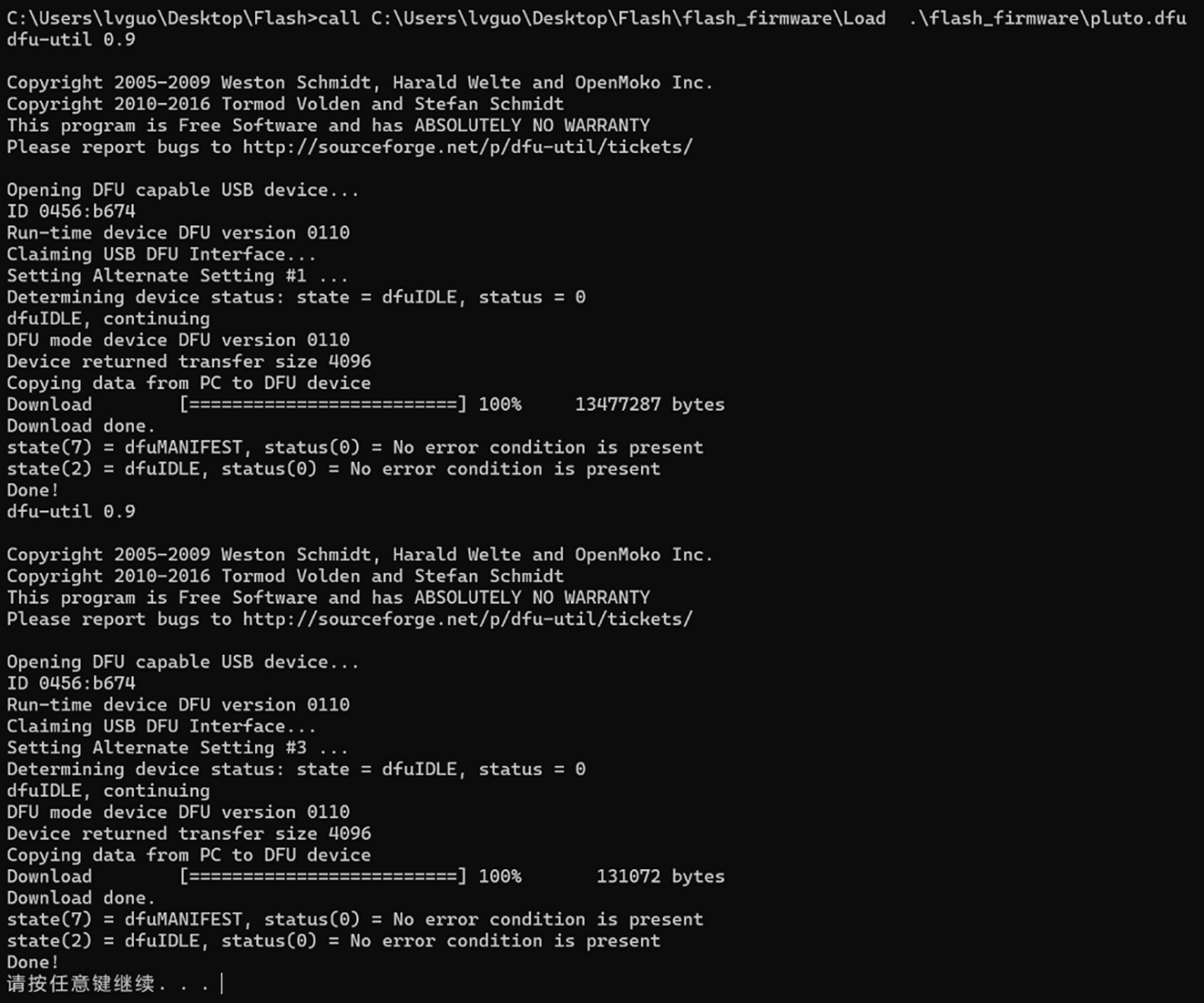
Open program_dfu.bat with Notepad++ or Sublime Text, not Notepad. Modify only the file path preceding /Load so that it points at the actual location of pluto.dfu and uboot-env.dfu, then save. Modify the path in Load.bat the same way. The two paths must match, and should avoid spaces and non-ASCII characters.
Both .dfu files are required. uboot-env.dfu cannot be skipped: the factory firmware relies on environment variables to present the AD chip as a 9361 rather than a 9363, and a unit recovered without them will connect but operate with restricted frequency and bandwidth.
Step 4 Program
Double-click program_dfu.bat and wait for the command-line download to complete. Then reboot the device.
8.7 Recovery Verification
Programming is successful when the DONE LED is on and the indicator LED blinks, or when the device is detected in IIO Oscilloscope through Setting → Connect.