1 Product Introduction
PlutoSky is a low-cost, portable software-defined radio (SDR) development platform. It is designed for education, research, and amateur radio enthusiasts. The core hardware architecture of PlutoSky is based on the Xilinx Zynq-7000 series SoC (for example, PlutoSky R1 is XC7Z020-2CLG400I, PlutoSky R2 is XC7Z020-2CLG484I). The RF front-end uses ADI's AD9361 or AD9363 series highly integrated RF Agile Transceiver.
Production Links:
PlutoSky R1 with PA or PlutoSky R1 without PA

2 Windows System Tutorial
PlutoSky communicates with the computer by default through a USB virtual network card or Ethernet port. Although its default IP address is 192.168.2.1 when it is manufactured, you can configure it flexibly according to the actual connection method. The following explains in two scenarios: USB direct connection and wired Ethernet port connection.
2.1 Using USB Virtual Bridge Connection and Required Drivers
When PlutoSky communicates with the computer via the USB interface, it does not directly transmit the raw I/Q data. Instead, it utilizes the USB virtual bridge (RNDIS + CDC-ACM) technology to simulate the device as a virtual Ethernet card + virtual serial port. Thus, the host can access PlutoSDR through standard network protocols (such as TCP/IP), significantly simplifying cross-platform compatibility.
Connection advantages:
①No additional network cables or routers required
②Plug and play (after installing the driver)
③Supports all networked tools such as SSH, IIO, MATLAB, GNU Radio, etc.
④Default IP address is 192.168.2.1
However, on Windows systems, the official driver must be manually installed; otherwise, the device will be displayed as "unknown device" or will not be recognized as a network interface.
2.1.1 PlutoSDR-M2k-USB-Drivers.exe installation
This is the USB virtual network card driver package provided by ADI, which is used to enable Windows to recognize the RNDIS network function of PlutoSDR.
Step 1: Download driver
You can obtain the driver in the following two ways:
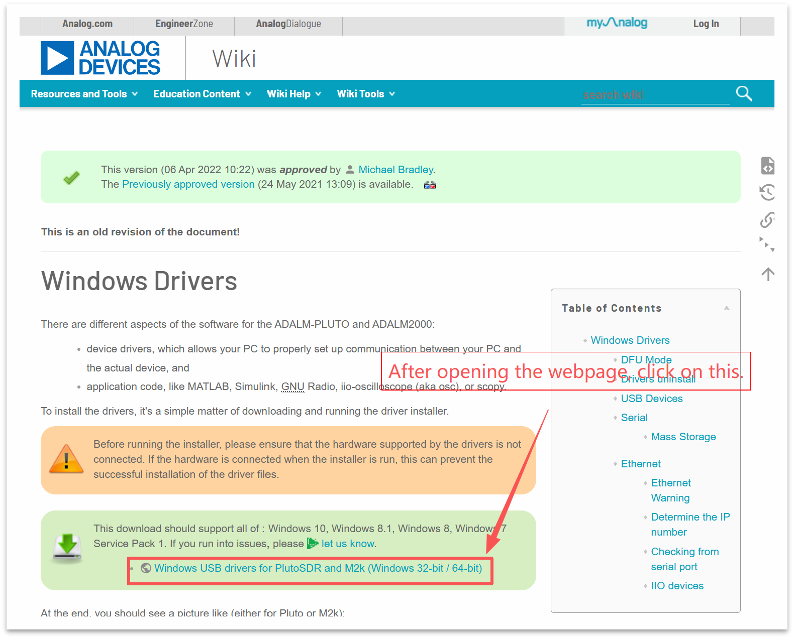
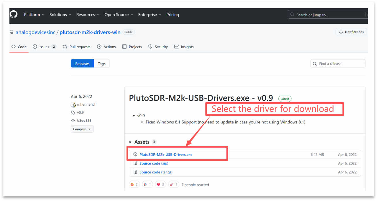
(1) The driver file is included in the resource package provided by us. The file is located in the "Windows system driver.exe file" folder. The file name is: PlutoSDR-M2k-USB-Drivers.exe

(2) You can obtain it from the ADI website:
https://wiki.analog.com/university/tools/pluto/drivers/windows
Step 2: Run the installation program
Run the installation program as an administrator. Double-click PlutoSDR-M2k-USB-Drivers.exe.
If a "Windows protects your PC" warning pops up, click "More Information" →"Still want to run".
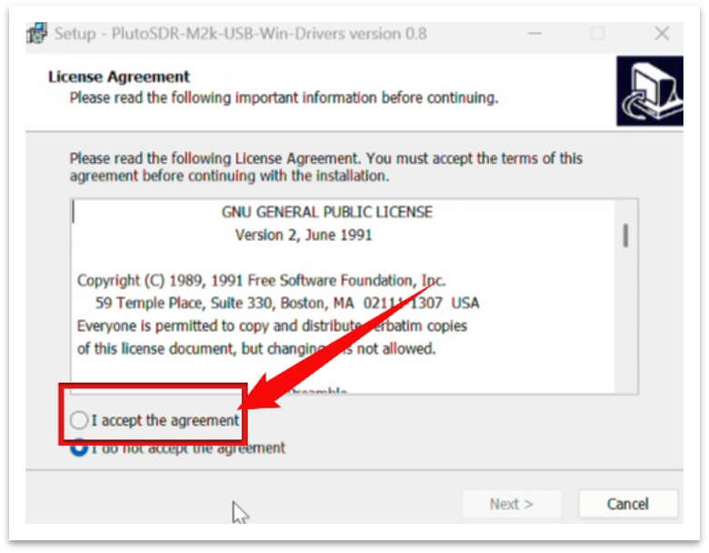
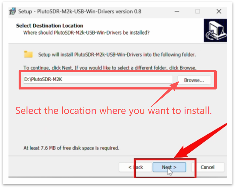
Follow the wizard to complete the installation.
Click "Next" →"I accept the agreement" →"Next" → "Install".
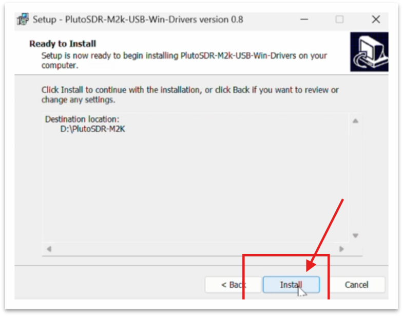
Wait for the driver files to be decompressed and registered (about 30 seconds)
Click "Finish" to complete.
Step 3: Connect PlutoSDR and verify
Insert the PlutoSDR into the computer using a USB data cable.
When connecting for the first time, Windows will automatically install "Analog Devices USB Device".
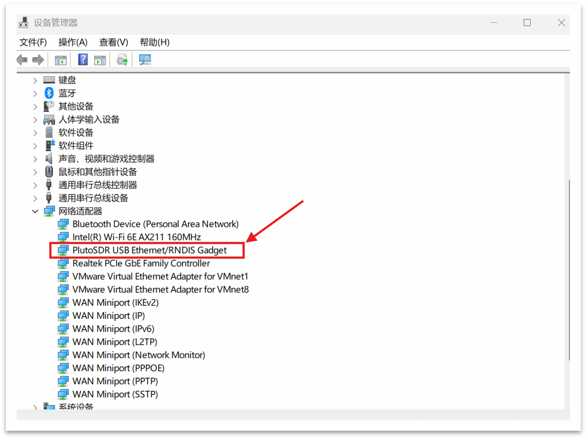
Open the Device Manager (Win+X → Device Manager):
You should see "Network Adapter" added under it: PlutoSDR USB Ethernet/RNDIS Gadget
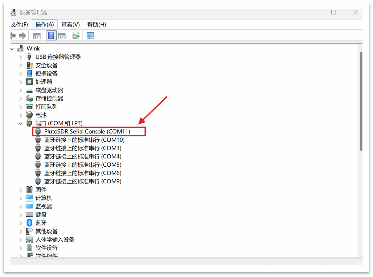
At the same time, the following appears under "Ports (COM and LPT)": PlutoSDR Serial Console (COMx)
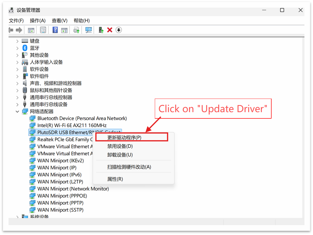
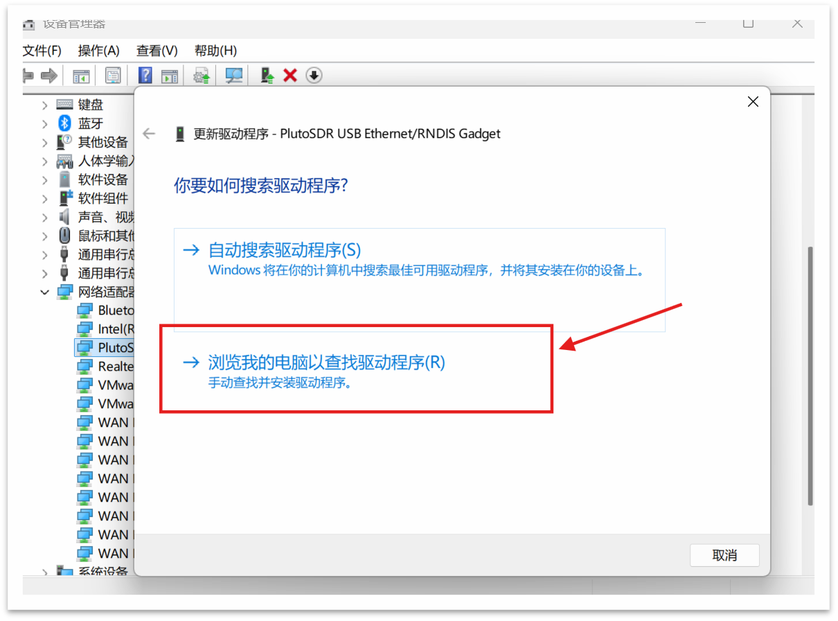
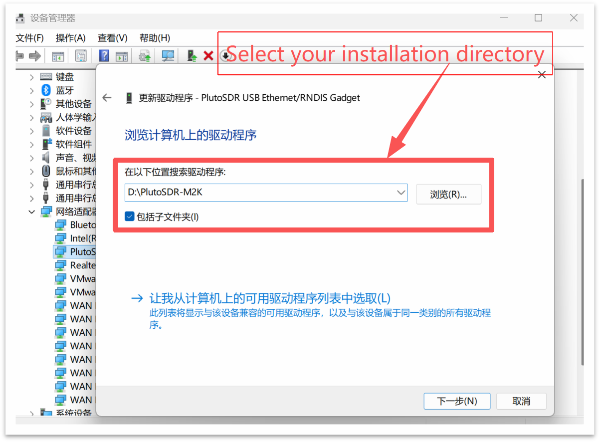
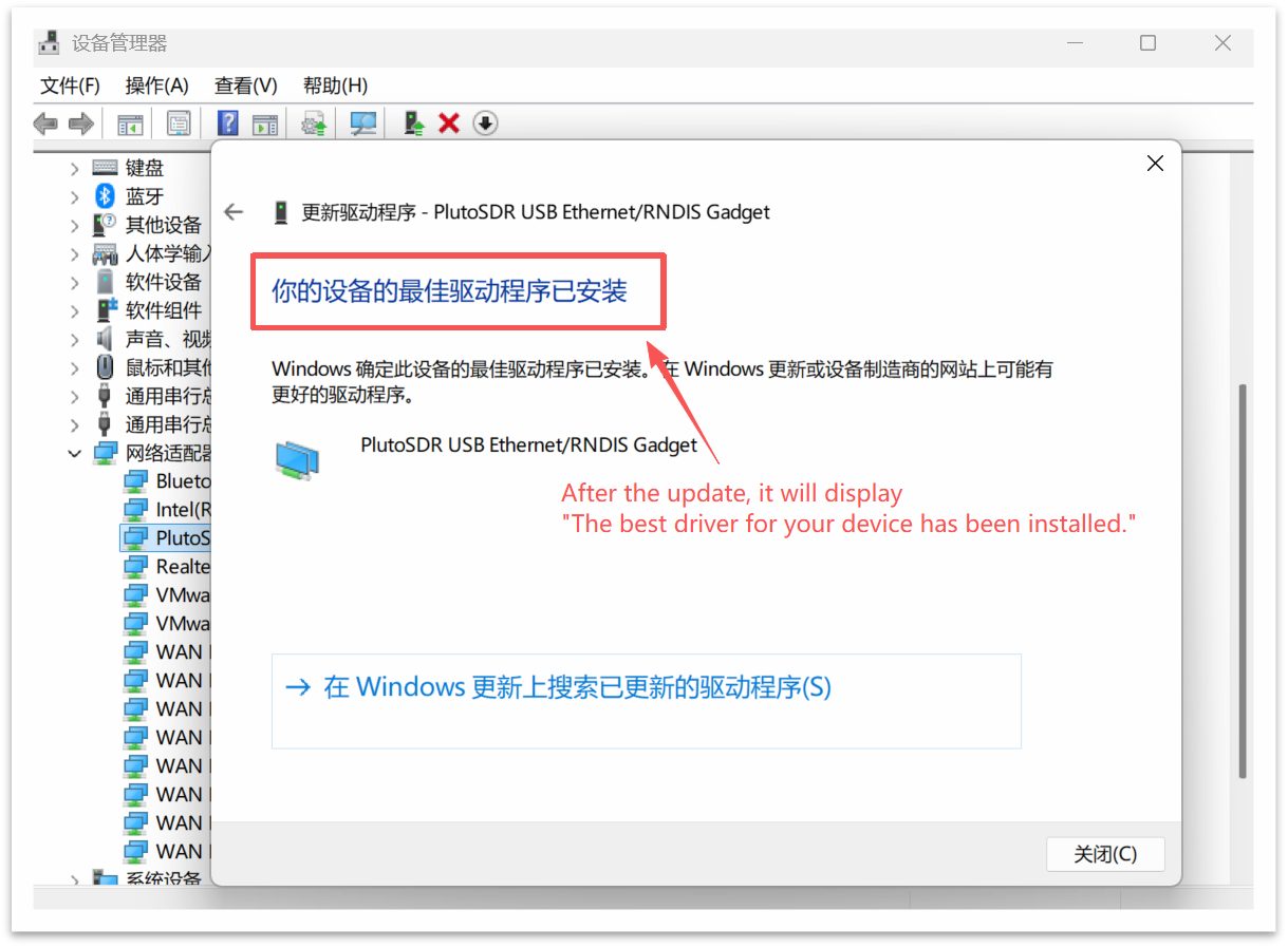
If it has not been automatically installed, right-click the device →"Update Driver" →"Browse my computer for drivers" →Select the folder located in the installation directory (either "win10" or "win7").
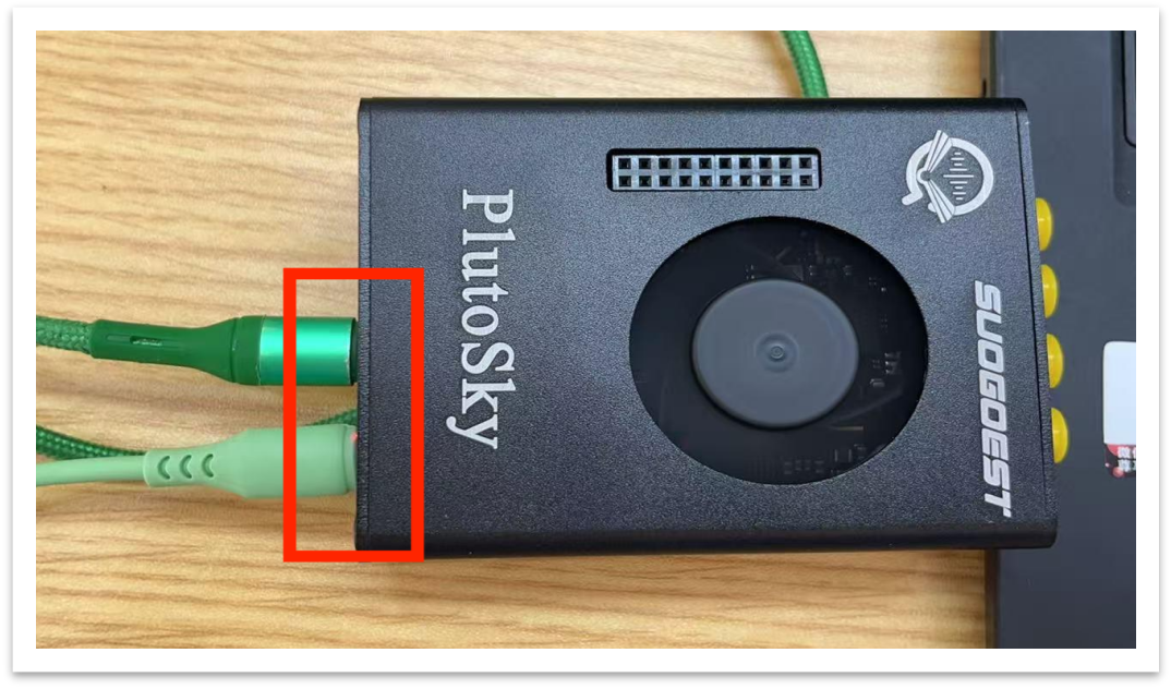
Note: If the PlutoSky device is not detected after connection, insufficient power supply may be the cause. Please connect both USB ports and try again.
2.2.2 Installation of libiio-setup.exe
Libiio (Industrial I/O Library) is a cross-platform communication library developed by ADI. All the upper-layer software on PlutoSDR (such as IIO-Scope, GNU Radio, MATLAB) rely on it.
LIBIIO-SETUP.EXE is its Windows installation package, which includes:
LIBIIO.DLL (core communication library)
IIO_INFO.EXE (device information query tool)
IIO_OSCILLOSCOPE.EXE (graphical debugging tool)
USB backend support (for USB virtual bridge communication)
Step 1: Download driver
You can obtain the driver in the following two ways:
(1) The driver file is included in the resource package provided by us.
The file is located in the "Windows system driver.exe file" folder. The file name is: libiio-0.26.ga0eca0d2-setup.exe

(2) You can obtain it from the ADI website:
https://github.com/analogdevicesinc/libiio/releases
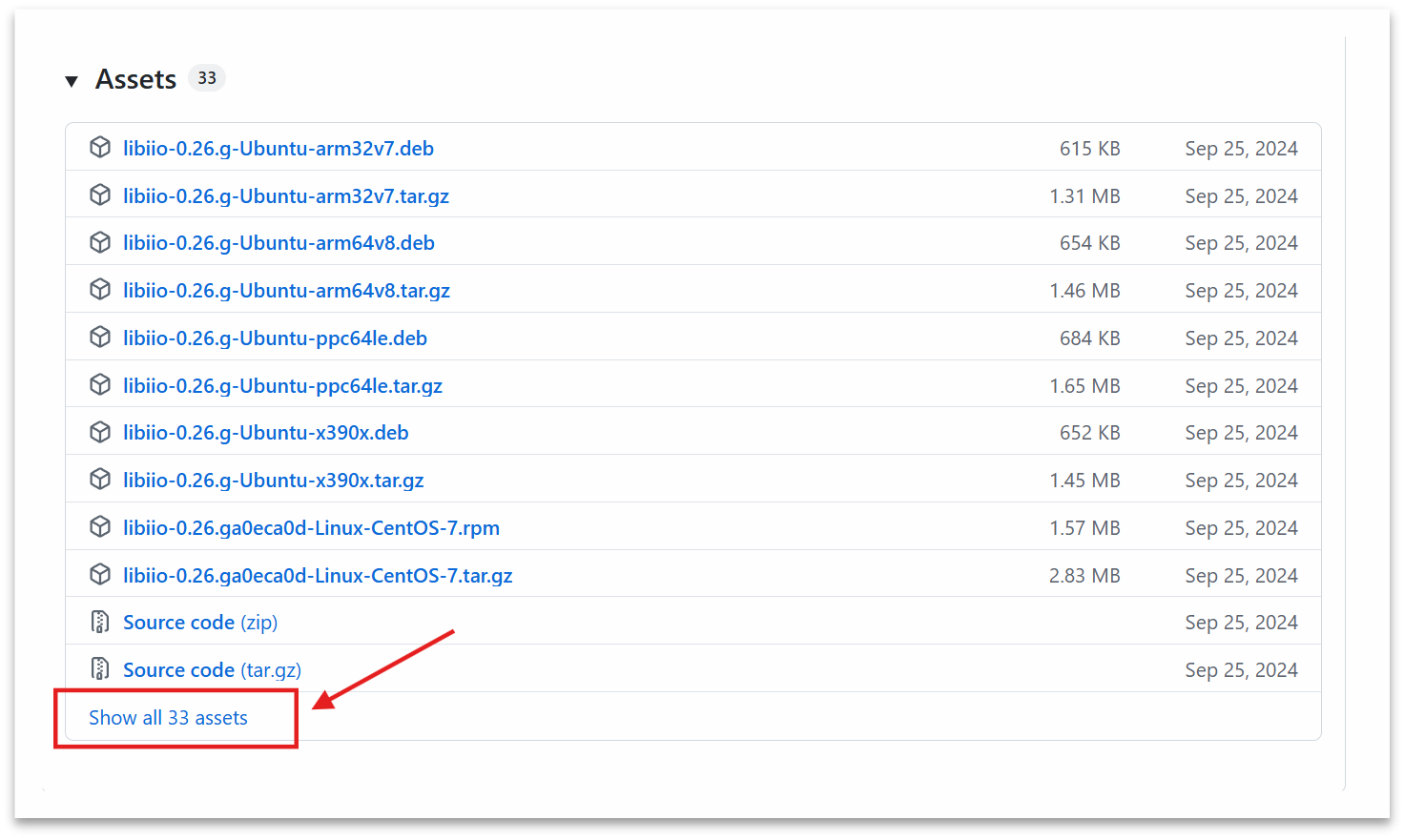
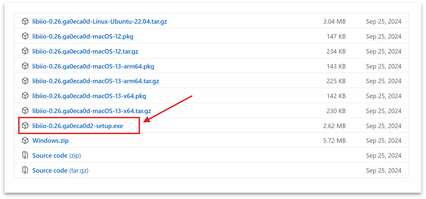
Step 2: Run the installation program
Double-click to run libiio-0.26.ga0eca0d2-setup.exe.
Select the language (English is recommended)
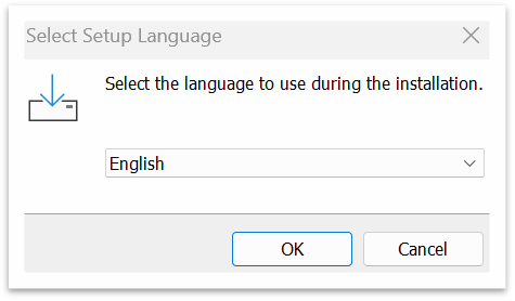
Click “OK”→“I accept the agreement”→“Next”
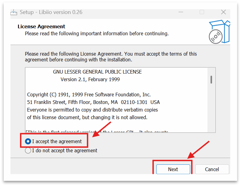
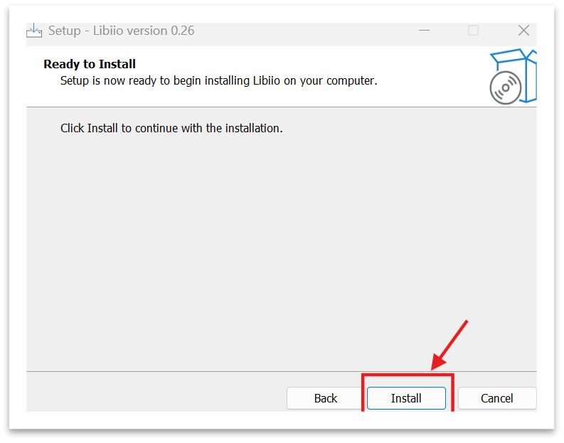
Click“Install”
Step 3: Verify successful installation
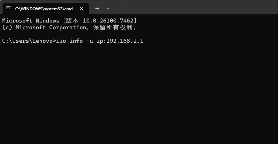
Open the Command Prompt (CMD) and enter:
iio_info -u ip:192.168.2.1
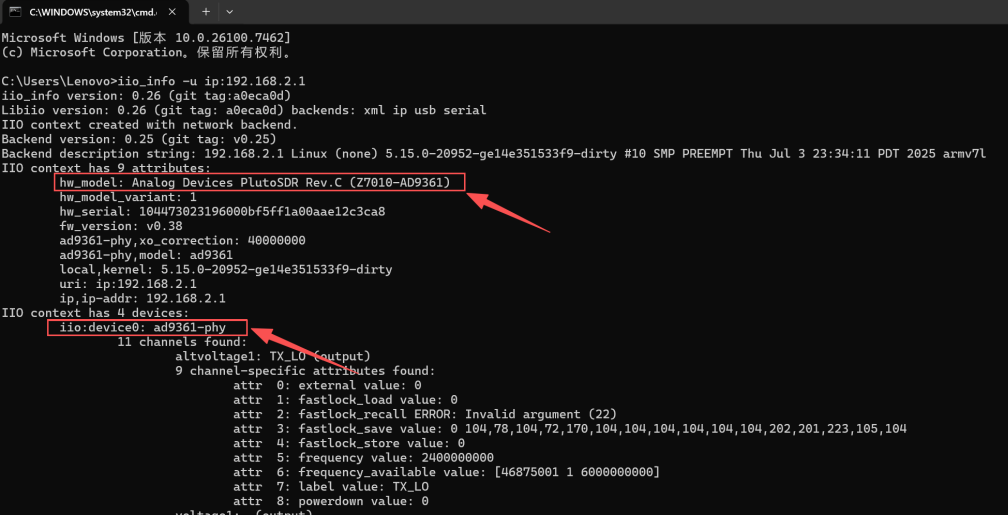
If the output shows the device information of PlutoSDR (such as ad9361-phy), it indicates that the communication is normal!
Note:
The USB driver must be installed first before libiio can find the device through the USB virtual bridge.
Before using iio_info for the first time, make sure the computer's IP address is set to 192.168.2.x.
2.2 Using network cable connection and required drivers
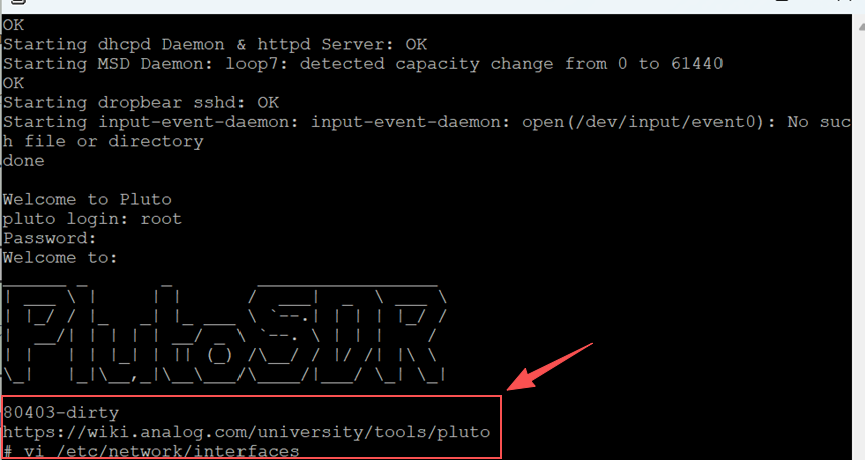
Step 1: Log in to PlutoSky via the debug port (to gain control)
Since you are unable to log in via the network, you need to use the debug port for debugging.
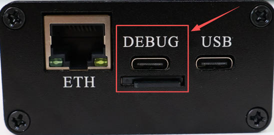
Prepare hardware: Connect the USB-C cable to the debug port (in the middle).
You need a software to act as the "terminal" for communicating with the serial port device. Here are some common options:
For Windows systems, use PuTTY or Tera Term.
On macOS/Linux systems, use screen or minicom.
Set the baud rate to 115200
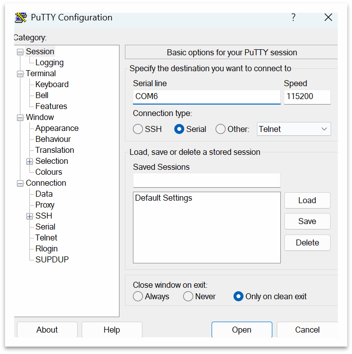
Log in to the system:
When "pluto login:" appears, enter:
Username: root
Password: analog
Step 2: Check the current network configuration
After logging in, enter the following command:
ifconfig
Or
cat /etc/network/interfaces
Step 3: Temporary modification of IP
Suppose you want to change it to 192.168.6.10 and the gateway to 192.168.6.1, execute:
# Set IP and subnet mask
ifconfig eth0 192.168.6.10 netmask 255.255.255.0 up
# Set default gateway (optional, for accessing the external network)
route add default gw 192.168.6.1
Step 4: Test the new IP
On the computer, change the network card IP to the same subnet (such as 192.168.6.20), and then ping:
ping 192.168.6.10
If it works, it means success!
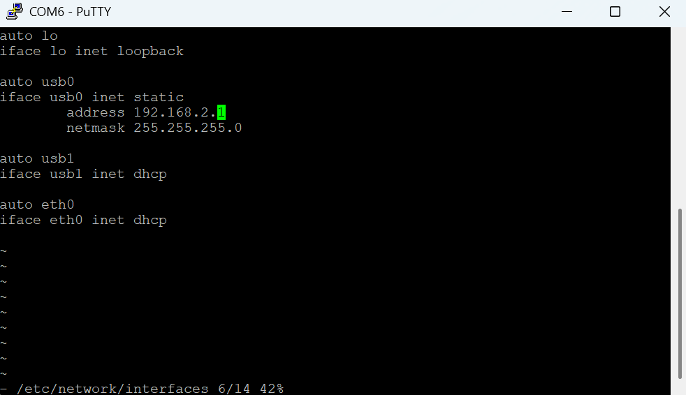
If you want to permanently modify IP, i.e., if you want the changes to remain effective after a reboot, you need to edit /etc/network/interfaces:
vi /etc/network/interfaces
Modify the "address" field, save the changes and then restart.
3 Ubuntu System Tutorial
4 Firmware Flashing Tutorial
Here is the Youtube Video for this part operations.
4.1 Three Boot Modes
There are three boot modes for the PlutoSky, i.e., JTAG boot mode, flash boot mode and SD card boot mode.
JTAG Mode
It is used for debugging and firmware flashing. It can flash firmware into the onboard Flash chip. Only JTAG mode supports flashing Flash firmware via VIVADO software in your computer. The PlutoSky does not have DFU button. VIVADO flashing will erase Flash and DFU firmware, and the device will automatically enter into DFU mode after power-on. The DFU boot mode is used to recover when custom programs are flashed into the onboard Flash chip and cause firmware errors.
Flash Mode
Load boot files from onboard Quad-SPI Flash chip.
SD Card Mode
Load boot files from TF card which contains boot.bin.
The PlutoSky supports both Flash boot and SD card boot by factory default.
4.2 DIP Switch Boot Mode Definition
4.2.1 DIP Switch Boot Mode Definition for PlutoSky R1
Note: DIP switch settings must be operated when the device is powered off. Settings are invalid under power-on state.
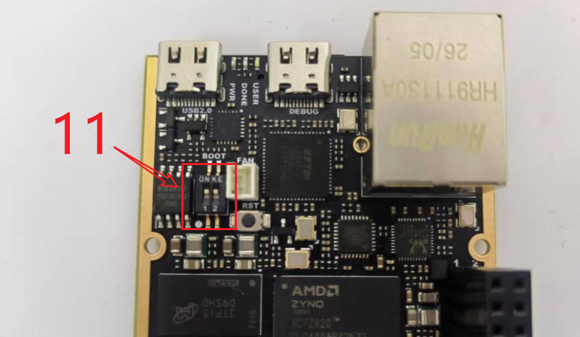
QSPI Boot Mode: Switch 1 connects to VCC 3V3, Switch 2 connects to GND. Factory default boot mode from onboard Flash.
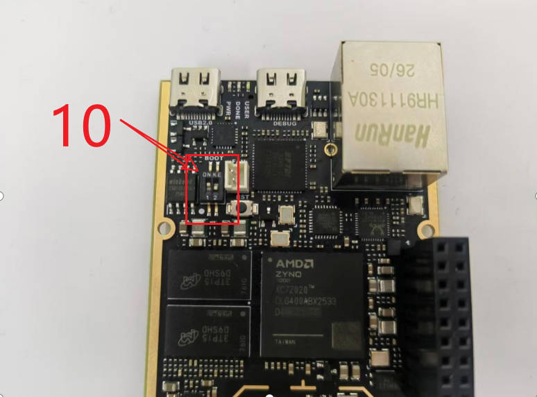
SD Card Boot Mode: Switch 1 connects to GND, Switch 2 connects to GND. Boot from microSD card with boot.bin.
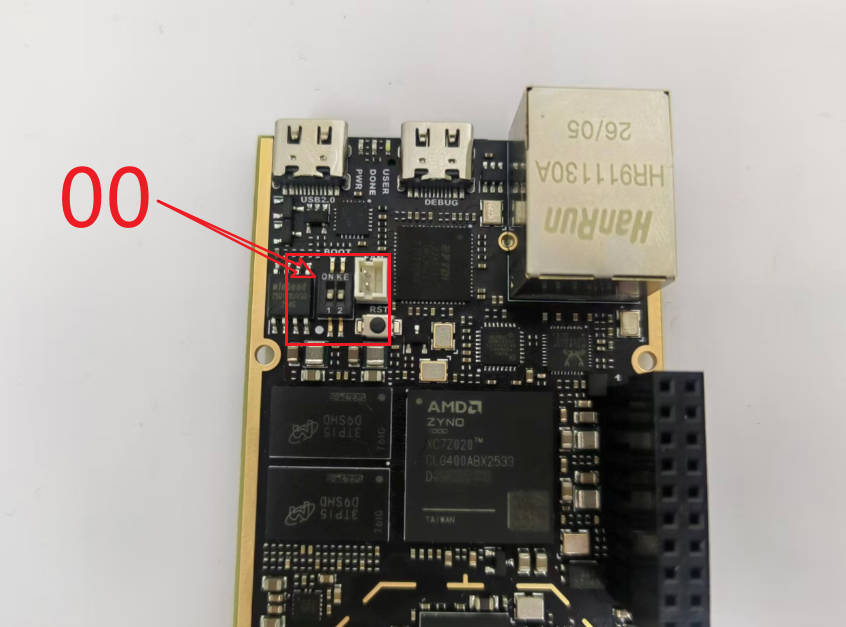
JTAG Debug Mode: Switch 1 connects to VCC3V3, Switch 2 connects to VCC3V3. Used for development debugging and firmware flashing.
4.2.2 DIP Switch Boot Mode Definition for PlutoSky R2
To be added later.
4.3 SD card firmware flashing
4.3.1 SD Card Burning Steps
If you want to use the SD card boot working mode, you need to do this SD card firmware flashing.
Please download SD FIRMWARE.rar.
Use a SD card and format it as FAT32 file system.
Copy all firmware files to the root directory of the SD card.
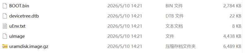
Power off the device, set DIP switch to SD card boot mode.
Insert the SD card into the slot, connect device USB port to PC. It will power on the device.
4.3.2 Verify SD Card Firmware
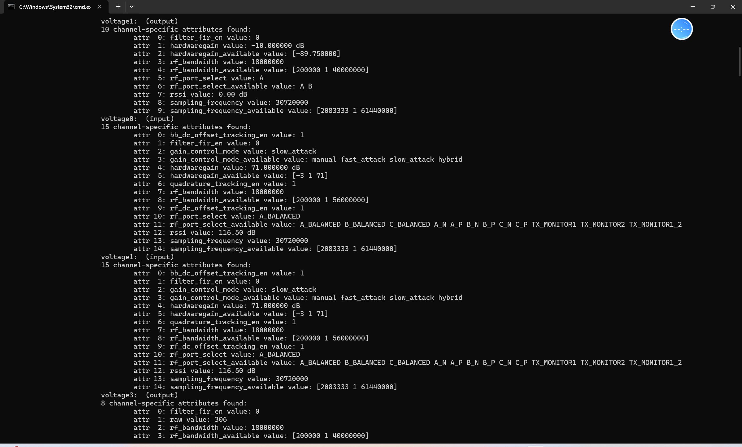
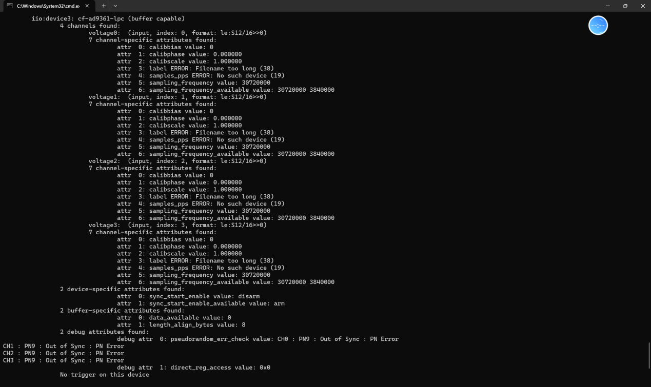
Method 1: Test via CMD command
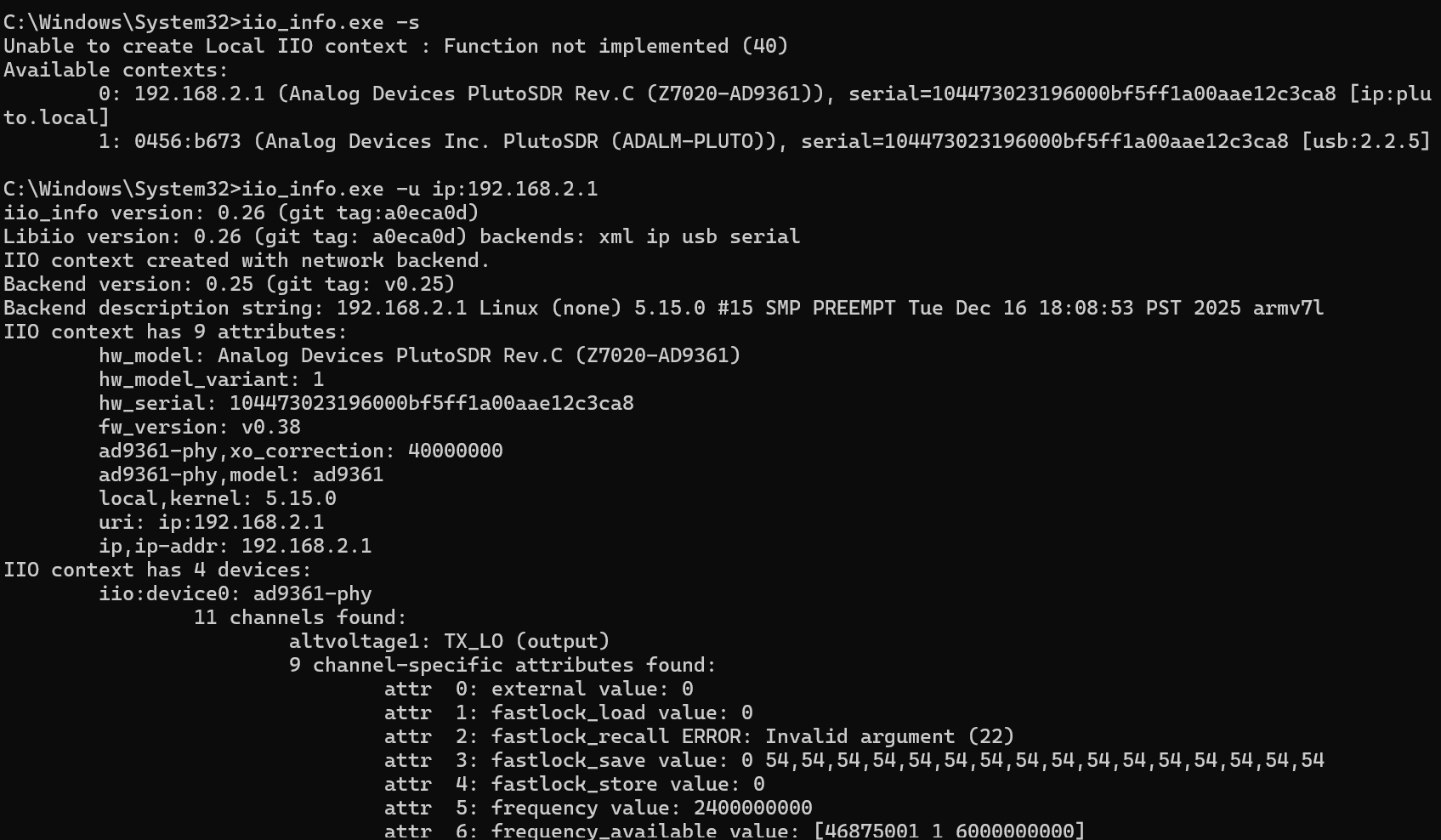
Open CMD in the folder of iio_info.exe, input one of the following commands:
iio_info.exe -s
iio_info.exe -u ip:192.168.2.1 or iio_info.exe -u ip:pluto.local
Note that if you use the SD card boot mode, the default IP address of the PlutoSky is 192.168.2.1. And you can also manually modify the IP address.
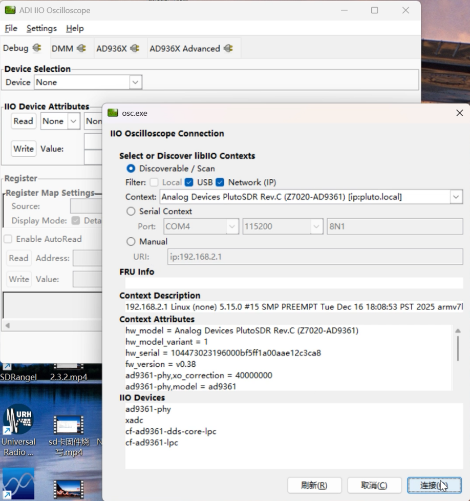
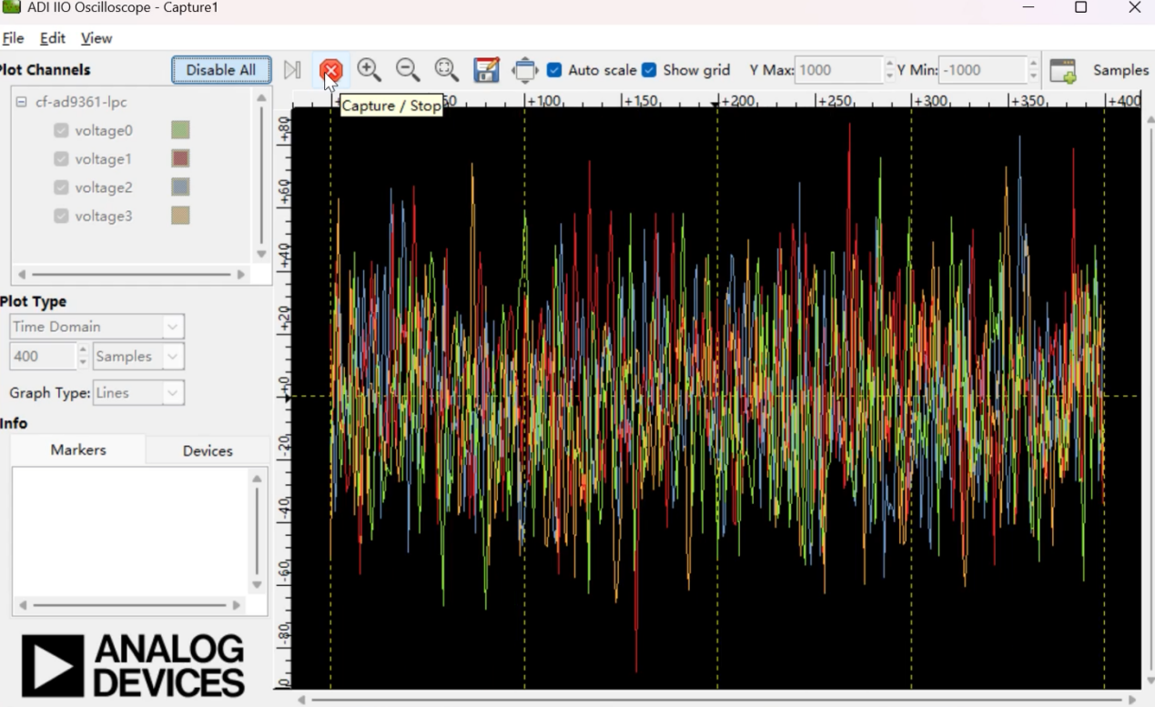
Method 2: Verify via IIO-Oscilloscope Software
Open IIO-Oscilloscope software, add new device, manually input IP: 192.168.2.1.
If the software recognizes AD9361 hardware and displays spectrum waveform, the firmware runs normally.
4.4 Flash Firmware via VIVADO in JTAG Mode
Note: The device is pre-burned with official firmware by factory default. Ordinary users do not need this operation.
This operation is only required when users use the board as a ZYNQ development board and flash custom programs, resulting in damaged and abnormal Flash firmware.
Enter JTAG Boot Mode
Switching the BOOT selector to JTAG when the device is powered off.
Hardware connection and power-on
Connect the PlutoSky’s DEBUG port to your computer via a Type C data cable. Power on the device; the POWER indicator will light up red.
Vivado Hardware Connection Operations
Launch the Vivado software → Click Open Hardware Manager → Wait for loading → Click Open target
Solutions for Device Not Recognized by Vivado
If Vivado fails to detect the device: Navigate to .../nt64/digilent, run install_digilent.exe as Administrator, follow the wizard to install the driver, restart your computer, then reopen Vivado.
Configure Storage and Program Files
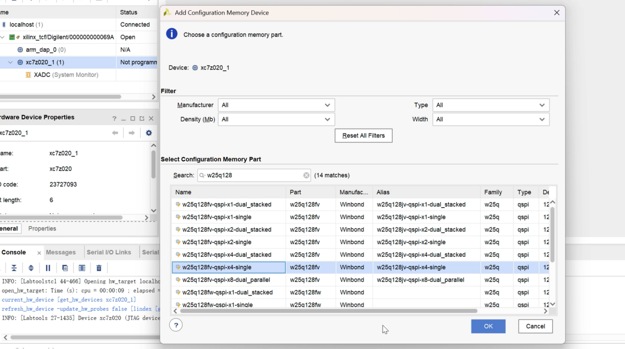
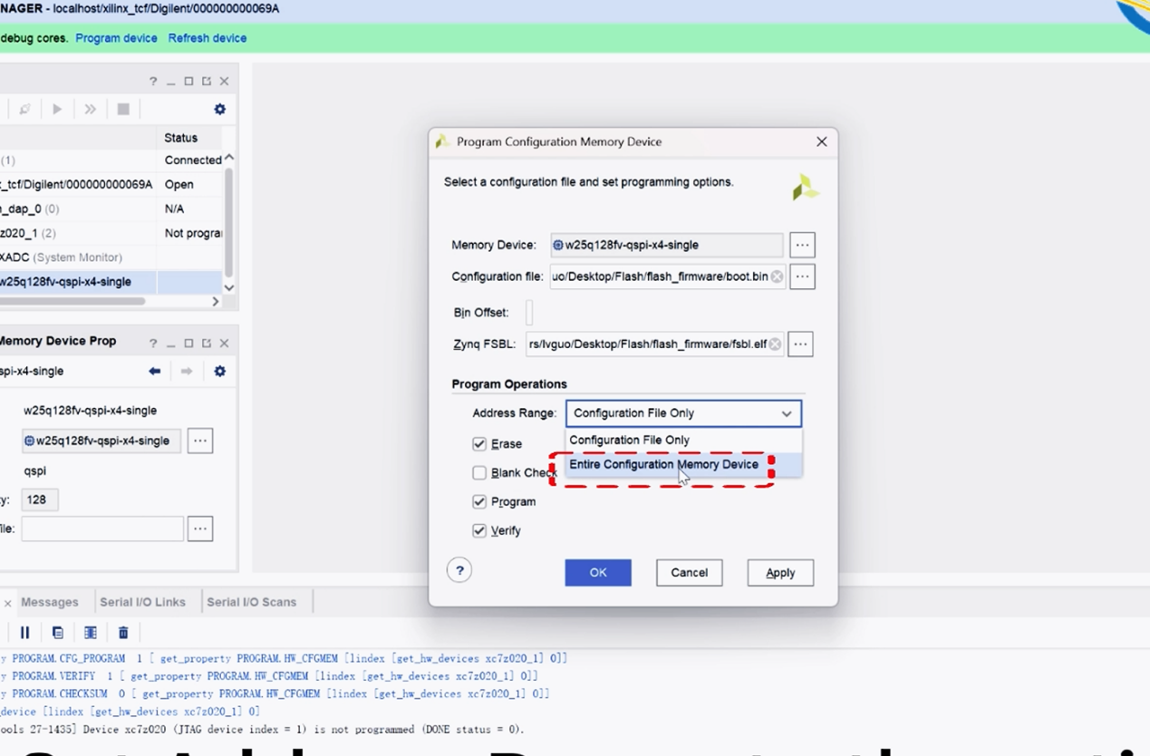
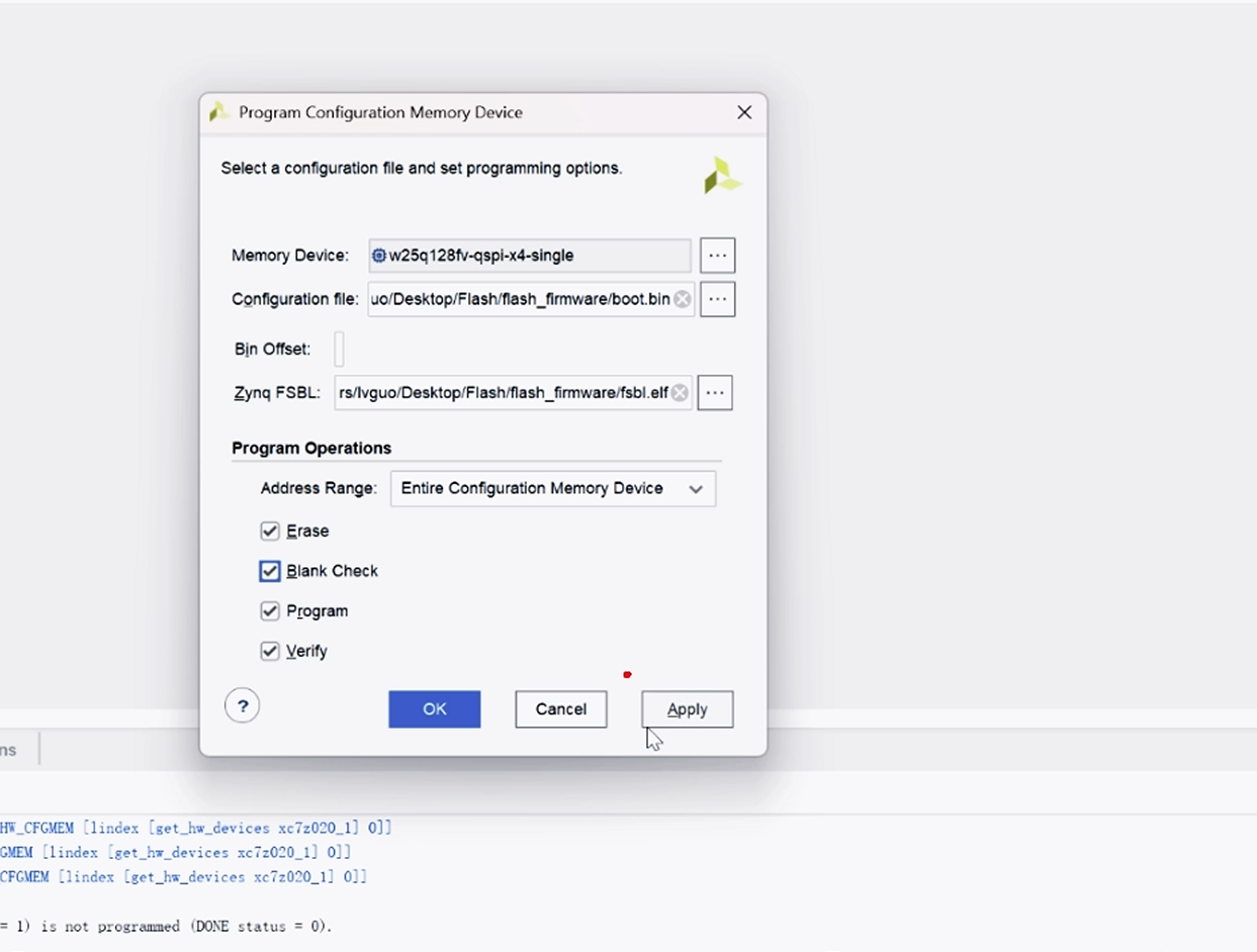
Once the device (e.g., xc7z020_1) is detected: Right-click and select Add Configuration Memory Device → Search for w25q128, select the x4 version and confirm → Import the provided boot.bin and fsbl.elf files → Set Address Range to the entire Flash → Check the 4 configuration options → Click Apply and wait 3-5 minutes for programming.
4.5 DFU firmware programming
Switch to Flash Boot Mode
Power off the device, switch the BOOT selector to Flash boot mode, then connect the device’s USB port to your computer via a data cable.
Verify the previous programming result
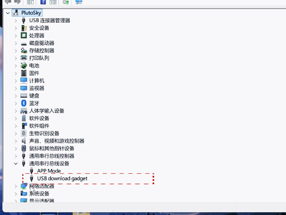
Open Device Manager on your computer; if USB download gadget appears under "Universal Serial Bus devices", the previous programming is successful. Otherwise, it means there was an error in the firmware flashing during the previous JTAG mode.
Modify the path of the programming script
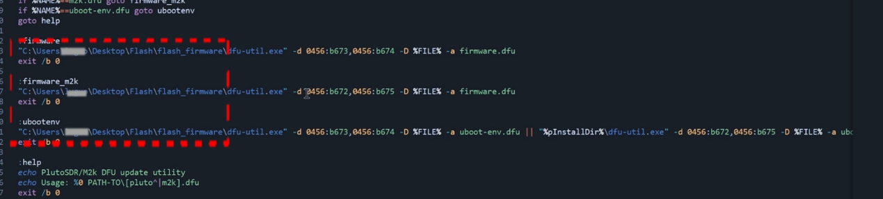
Open program_dfu.bat (in this Flash DFU FIRMWARE.rar) with Notepad++/Sublime Text. Only modify the file path before /Load (point to the location of pluto.dfu and uboot-env.dfu), save the file.
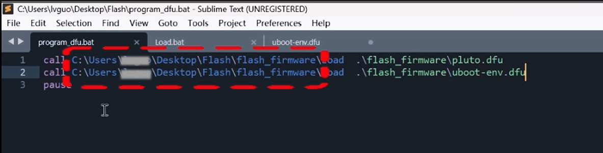
Then modify the path in Load.bat in the same way.
Perform DFU programming and verification
Double-click program_dfu.bat and wait for automatic downloading via the command line.
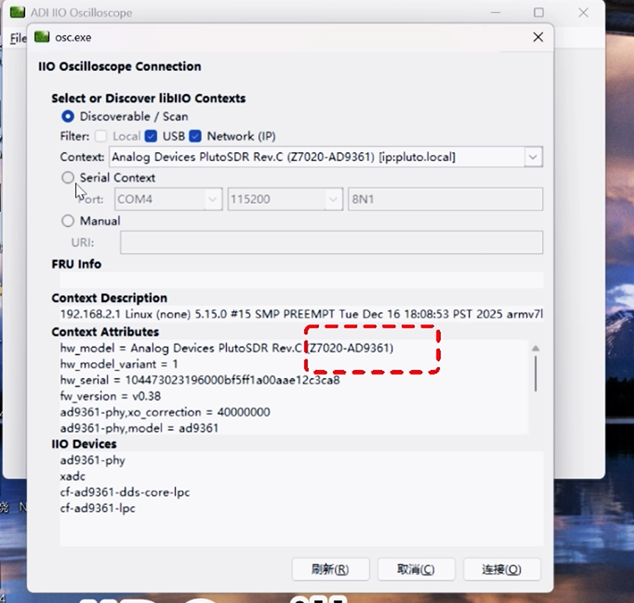
Reboot the device: Programming is successful if the DONE LED is on and the USER LED blinks, or the device is detected in IIP Oscilloscope via Setting→Connect.
5 PlutoSky Vivado Project Code
5.1 PlutoSky R1 Version
If you are using the PlutoSky R1 with PA or PlutoSky R1 without PA, please download the Vivado project code.
5.2 PlutoSky R2 Version
If you are using the PlutoSky R2, please download the Vivado project code.
To be continued later......