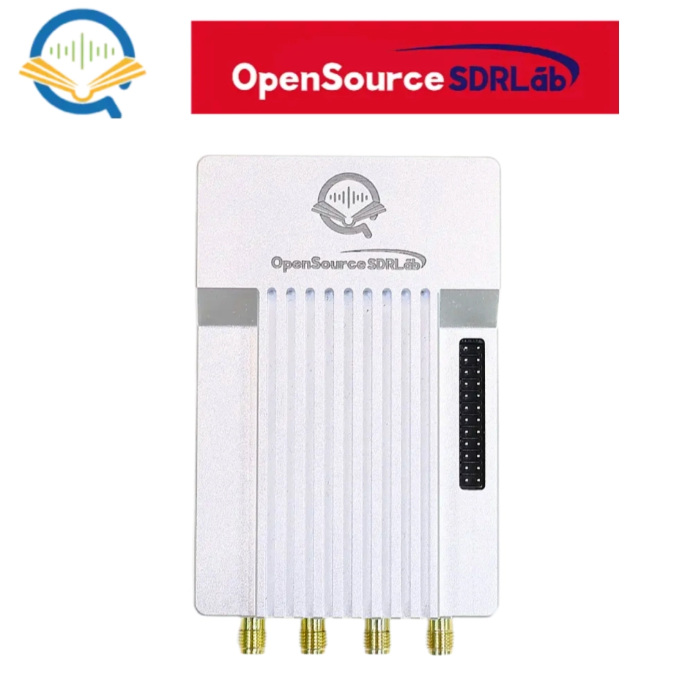
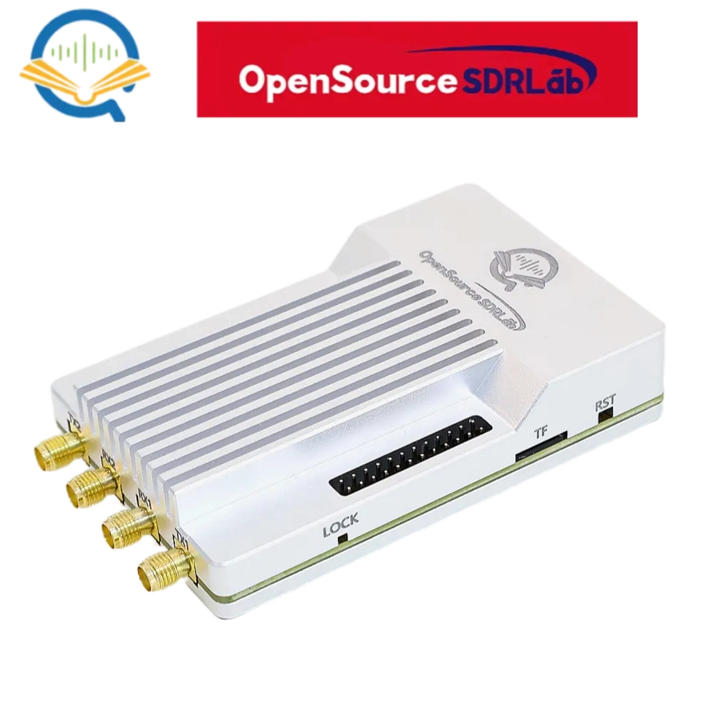
Product Introduction
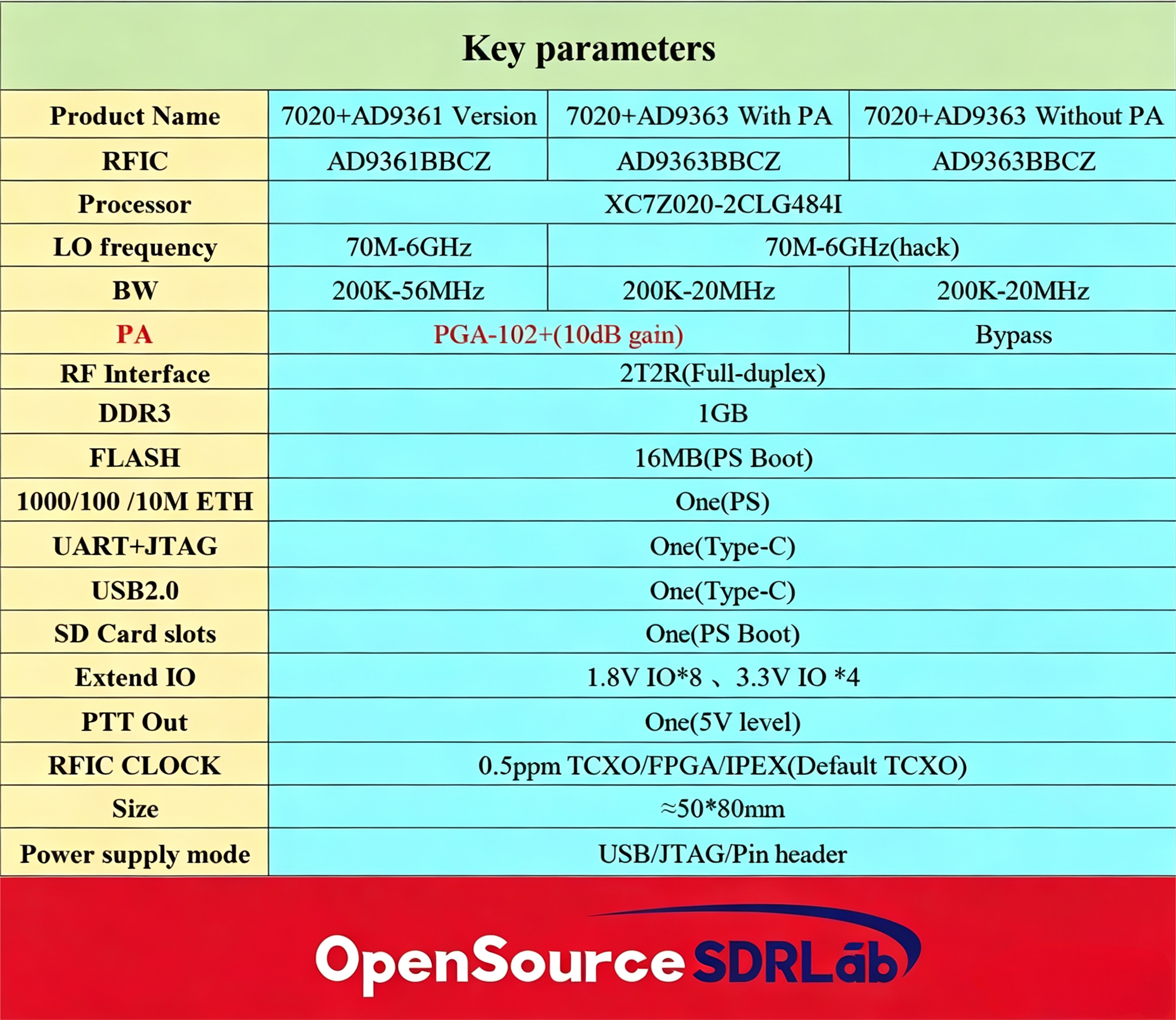
PlutoSky R2 is an upgraded high-performance software-defined radio (SDR) development platform launched by OpenSourceSDRLab, based on the classic ADALM-Pluto architecture. It adopts hardware main chip upgrade, abundant peripheral resources expansion, onboard hardware phase-locked loop and PL-side Ethernet optimization. It supports 70MHz-6GHz frequency range by firmware hack, 200K~20MHz bandwidth and full-duplex transceiver.
The core hardware adopts Xilinx Zynq XC7Z020-2CLG484I SoC, integrating dual-core ARM Cortex-A9 Processor System (PS) and FPGA Programmable Logic (PL). The RF front-end is equipped with AD9363 or AD 9361 RFIC, please choose the correct bundle in the product link.
Production Links: PlutoSky R2
PlutoSky R2 Hardware Upgrade & Highlight Spec
Main hardware updates for the PlutoSky R2
1.The main chip has been replaced with XC7Z020-2CLG484I (formerly XC7Z020-2CLG400I), which has more resources. XC7Z020-2CLG484 has the same Z-7020 core resources, but offers much more usable external I/O.
2.Added a 10MHz reference clock, which can be used to lock the onboard crystal oscillator.
3.Short circuit with 2.54mm jumper cap, you can choose to use an external 40MHz clock (note that the device needs to have onboard Flash firmware and the jumper cap should be operated to short circuit the device when it is powered off).
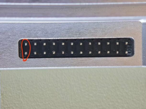
Fig. 1 Onboard flash firmware boot mode using the jumper cap can be connected in this way to directly use an external 40M clock input
As shown in Figure 2, users can also use GPIO to control whether to use an external 40MHz clock or an internal onboard 40MHz clock (note that the device needs to be Tezuka firmware that requires an SD card, and the device needs to perform jumper cap short circuiting operation when powered off).
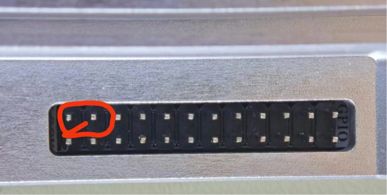
Fig. 2 SD card firmware boot mode using GPIO to control whether to use an external 40MHz clock or an internal onboard 40MHz clock
4.The network port has been added to the PL end (FPGA programmable logic program logic) instead of the traditional PS end (processor system PS). Customers can directly use logical resources for data transmission without the need for ARM cores to achieve data transparency.
Highlight Features
1. Two sets of firmware are pre installed on the board at the factory. The SD card firmware defaults to burning Tezuka firmware, which is compatible with PlutoSky R2 and will be continuously updated with new features; The onboard Flash firmware defaults to flashing the original ADALM PlutoSDR modified firmware.
2. Onboard hardware phase-locked loop, calibrated with a 10MHz reference to onboard 40M crystal oscillator. However, this product is a phase-locked loop implemented through hardware, and its performance is superior to software phase-locked loops of other similar products.
3. The board supports external GPIO expansion, and expansion daughter cards will be introduced in the future.
4. The product can be optionally equipped with an amplifier at the shooting end. Please distinguish between SKUs.
Hardware Specifications:
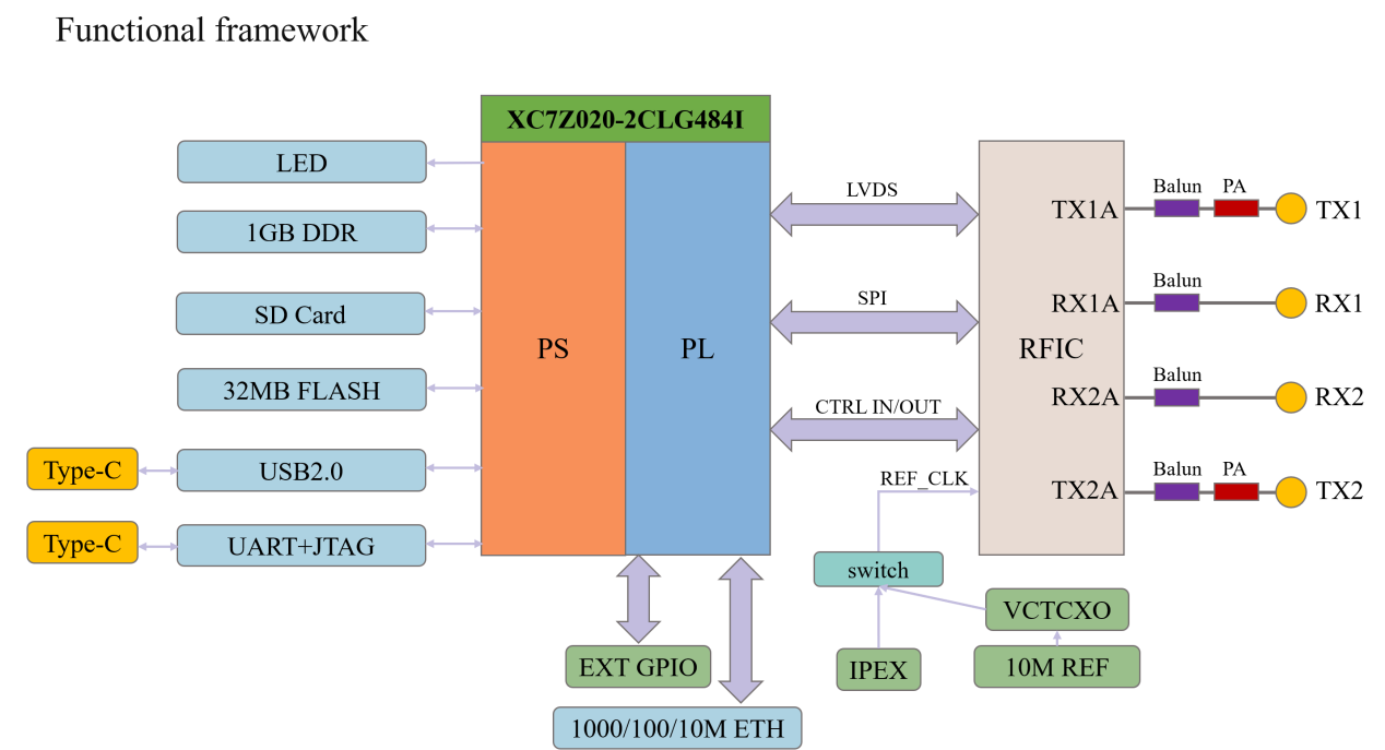
Functional Framework Description
The core architecture adopts Xilinx Zynq SoC, divided into PS (Processor System) and PL (Programmable Logic):
PS part: Equipped with 1GB DDR3 and 32MB SPI Flash, matches SD card boot circuit, UART/JTAG, USB 2.0 and power management modules.
PL part: Integrates Gigabit Ethernet, LVDS, Balun radio frequency matching circuit, and peripheral control circuits.
RF part: Matches dual-transmit dual-receive RF channels, optional PA modules, 10MHz reference clock, VCTCXO and external clock input interfaces.
Expansion part: Reserved external GPIO interfaces for secondary development and expansion daughter boards.
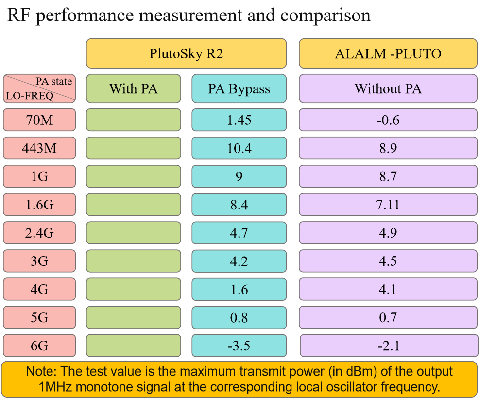
RF Performance Test Data
The table below shows the maximum transmit power (dBm) of 1MHz single-tone signal at different local oscillator frequencies. Comparison between PlutoSky R2 and standard ADALM-PLUTO (with/without PA, PA bypass state):
Functional framework
AD936x Series Chips
The Method Of Connecting To The Computer
List of Required Drivers and Software Dependencies
Startup Method and Firmware Architecture Details
The firmware included in PlutoSky R2 are the following.
Key point: The FPGA bitstream is not an independent startup item. Instead, it is loaded into the PL at runtime by the Linux kernel through the devicetree and firmware_class mechanism.
Built-in Flash firmware vs SD card firmware
Default startup behavior
Open Source Sources
Github Repo
Hardware Schematic file
Firmware Files
Vivado Project
PlutoSky R2 Vivado2021.1 project.rar
Frequently asked questions (FAQs)
1. Does the device support PPS (Pulse Per Second) input?
Answer: PPS calibration of onboard clock is not supported. However, when using an onboard 40MHz clock, it supports calibrating the onboard clock with a 10MHz input.
2. What are the functions of the three internal IPEX connectors on the circuit board?
Answer: They are 40M clock input, TX local oscillator, and RX local oscillator.
3.Does the device support internal clock and external clock switching?
Answer: PlutoSky R2 supports GPIO settings to determine whether to use an onboard 40MHz clock or an external 40MHz clock.
Windows System Usage Tutorial
PlutoSky R2 Windows User Manual Youtube Video
PlutoSky R2 communicates with the computer by default through a USB virtual network card or Ethernet port. Although its default IP address is 192.168.2.1 when it is manufactured, you can configure it flexibly according to the actual connection method. The following explains in two scenarios: USB direct connection and wired Ethernet port connection.
Using USB Virtual Bridge Connection and Required Drivers
When PlutoSky R2 communicates with the computer via the USB interface, it does not directly transmit the raw I/Q data. Instead, it utilizes the USB virtual bridge (RNDIS + CDC-ACM) technology to simulate the device as a virtual Ethernet card + virtual serial port. Thus, the host can access PlutoSky R2 through standard network protocols (such as TCP/IP), significantly simplifying cross-platform compatibility.
Connection advantages:
①No additional network cables or routers required
②Plug and play (after installing the driver)
③Supports all networked tools such as SSH, IIO, MATLAB, GNU Radio, etc.
④Default IP address is 192.168.2.1
However, on Windows systems, the official driver must be manually installed; otherwise, the device will be displayed as "unknown device" or will not be recognized as a network interface.
PlutoSDR-M2k-USB-Drivers.exe installation
This is the USB virtual network card driver package provided by ADI, which is used to enable Windows to recognize the RNDIS network function of PlutoSDR.
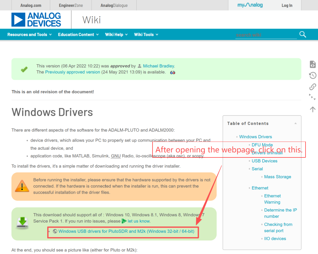
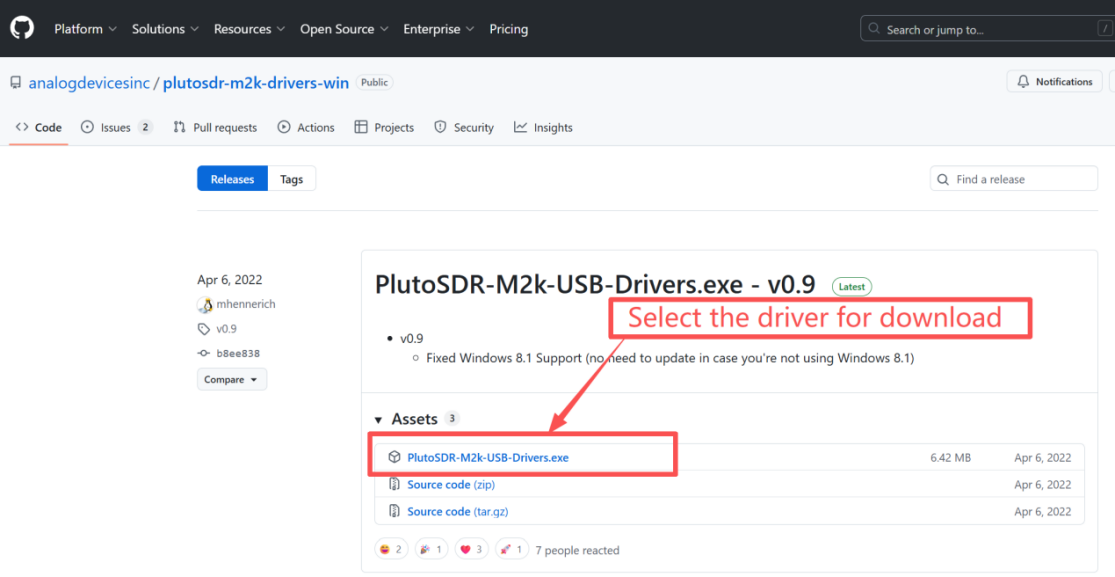
Step 1: Download driver
You can obtain the driver in the following two ways:
The driver file is included in the resource package.
The file is located in the "Windows system driver.exe file" folder. The file name is: PlutoSDR-M2k-USB-Drivers.exe

You can obtain it from the ADI website:
https://wiki.analog.com/university/tools/pluto/drivers/windows
Step 2: Run the installation program
Run the installation program as an administrator.
Double-click PlutoSDR-M2k-USB-Drivers.exe.
If a "Windows protects your PC" warning pops up, click "More Information" →"Still want to run".
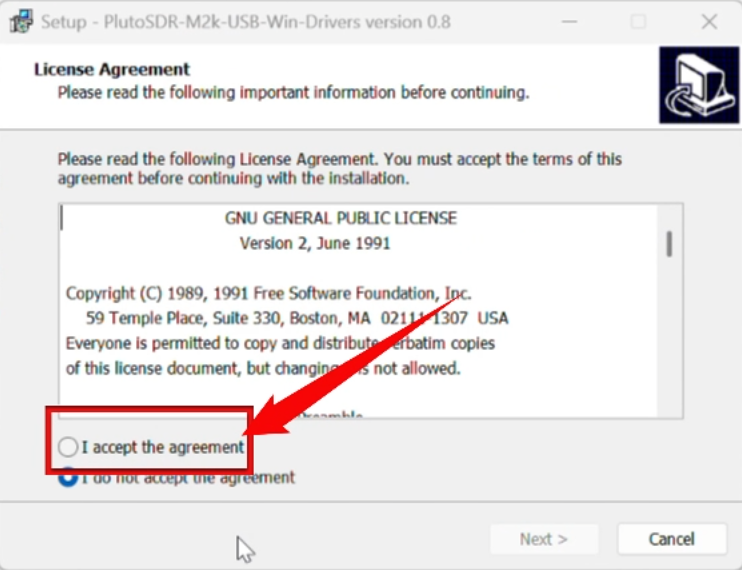
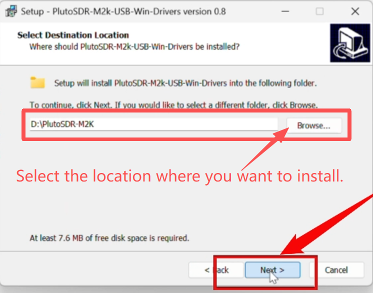
Follow the wizard to complete the installation.
Click "Next" →"I accept the agreement" →"Next" → "Install".
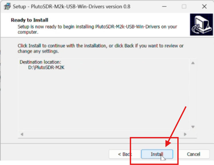
Wait for the driver files to be decompressed and registered (about 30 seconds)
Click "Finish" to complete.
Step 3: Connect PlutoSky R2 and verify
Insert the PlutoSky R2 into the computer using a USB data cable.
When connecting for the first time, Windows will automatically install "Analog Devices USB Device".
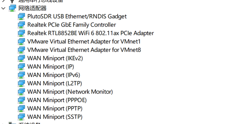
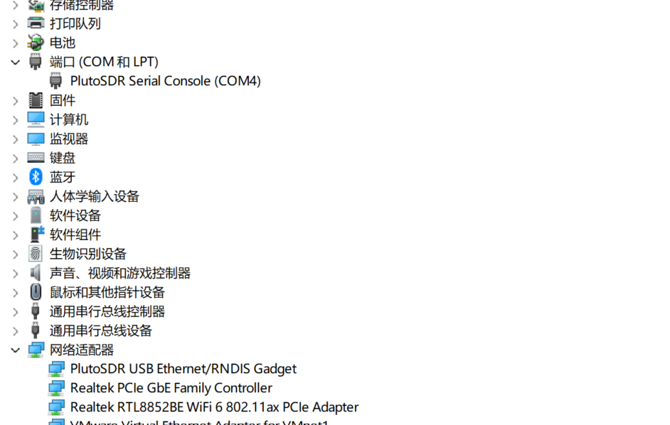
Open the Device Manager (Win+X → Device Manager):
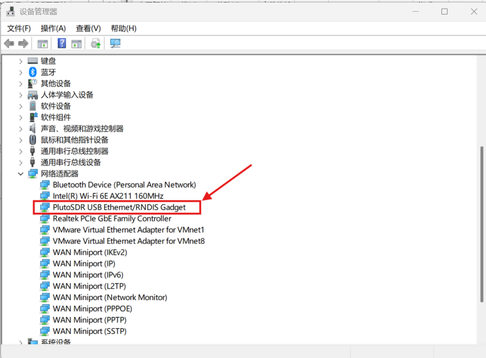
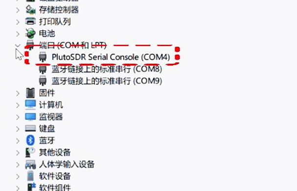
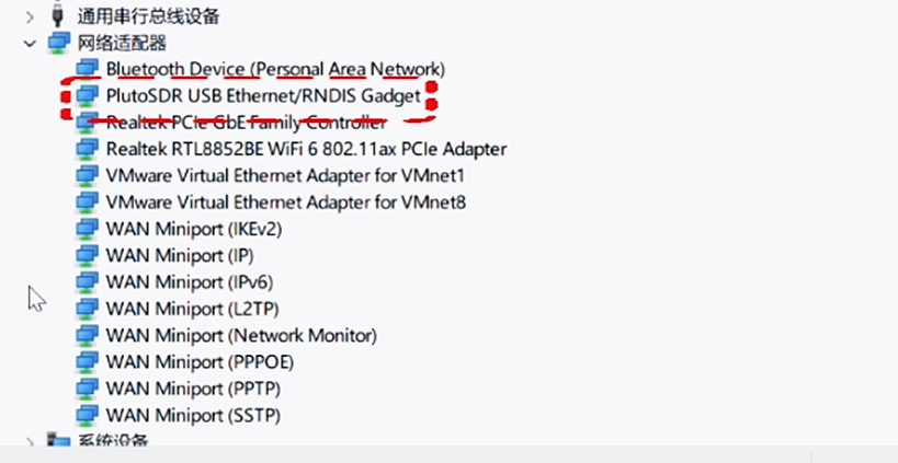
You should see "Network Adapter" added under it: PlutoSDR USB Ethernet/RNDIS Gadget
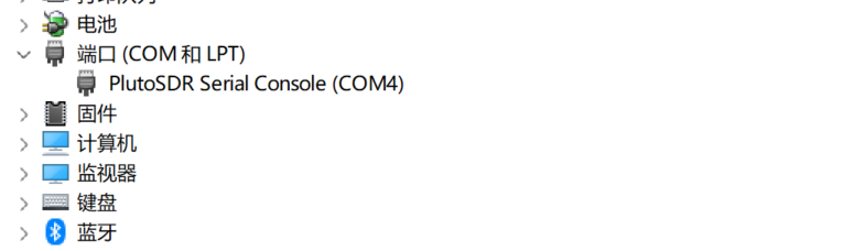
At the same time, the following appears under "Ports (COM and LPT)": PlutoSDR Serial Console (COMx)
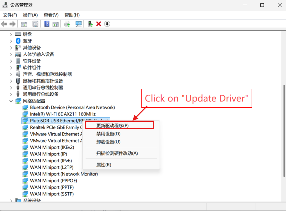
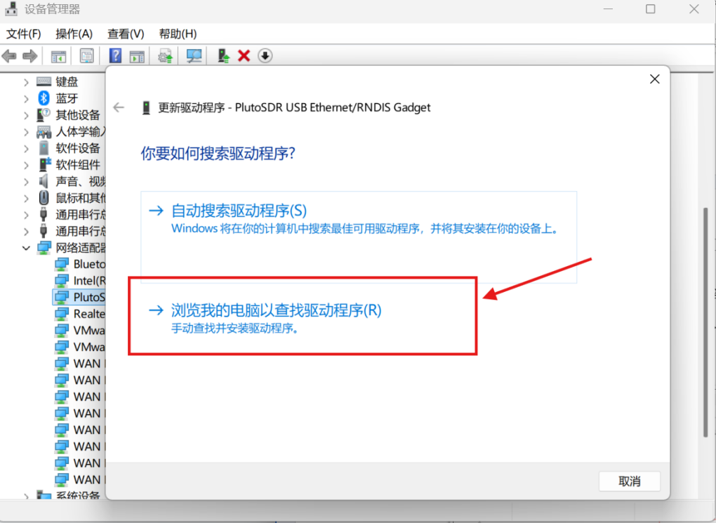
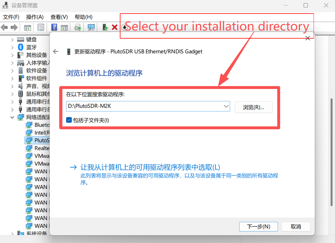
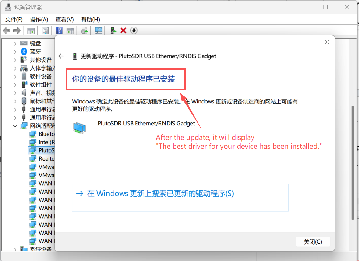
If it has not been automatically installed, right-click the device →"Update Driver" →"Browse my computer for drivers" →Select the folder located in the installation directory (either "win10" or "win7").
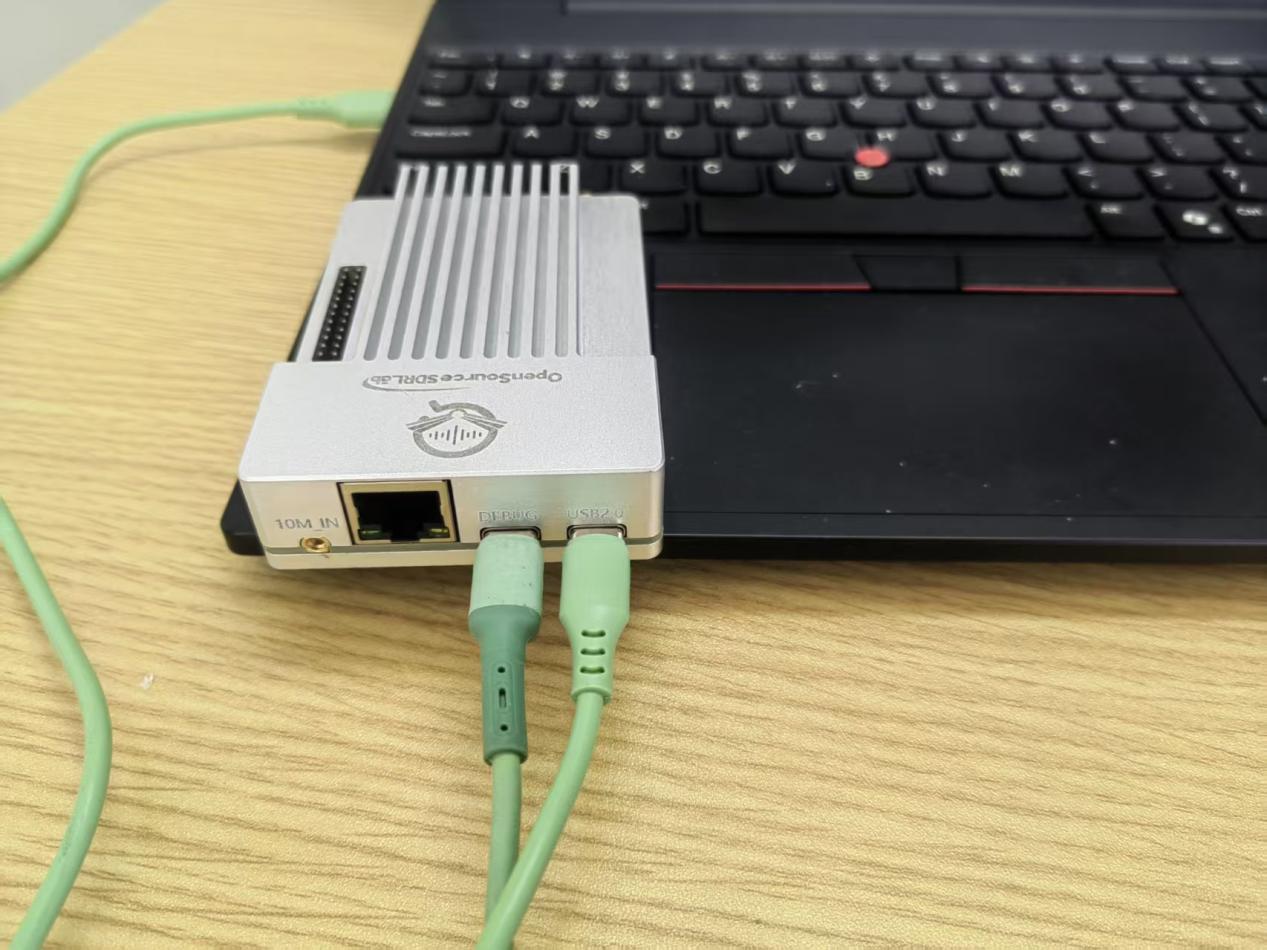
Note: If the Pluto device is not detected after connection, insufficient power supply may be the cause. Please connect both USB ports and try again.
Installation of libiio-setup.exe
Libiio (Industrial I/O Library) is a cross-platform communication library developed by ADI. All the upper-layer software on PlutoSky R2 (such as IIO-Scope, GNU Radio, MATLAB) rely on it.
LIBIIO-SETUP.EXE is its Windows installation package, which includes:
LIBIIO.DLL (core communication library)
IIO_INFO.EXE (device information query tool)
IIO_OSCILLOSCOPE.EXE (graphical debugging tool)
USB backend support (for USB virtual bridge communication)
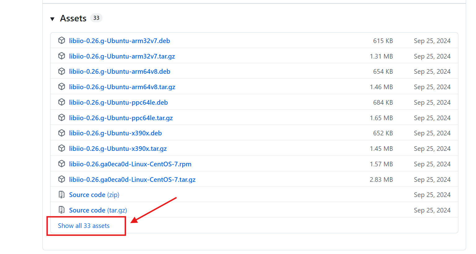
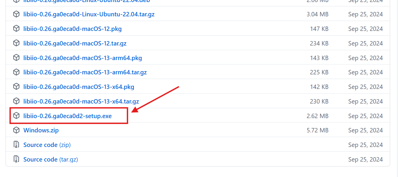
Step 1: Download driver
1.You can obtain the driver in the following two ways:
The driver file is included in the resource package.
The file is located in the "Windows system driver.exe file" folder. The file name is: libiio-0.26.ga0eca0d2-setup.exe

2.You can obtain it from the ADI website:
https://github.com/analogdevicesinc/libiio/releases
Step 2: Run the installation program
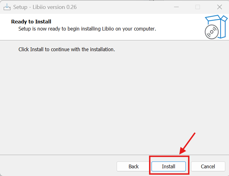
Double-click to run libiio-0.26.ga0eca0d2-setup.exe.
Select the language (English is recommended)
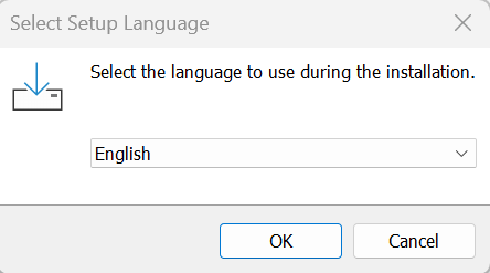
Click “OK”→“I accept the agreement”→“Next”
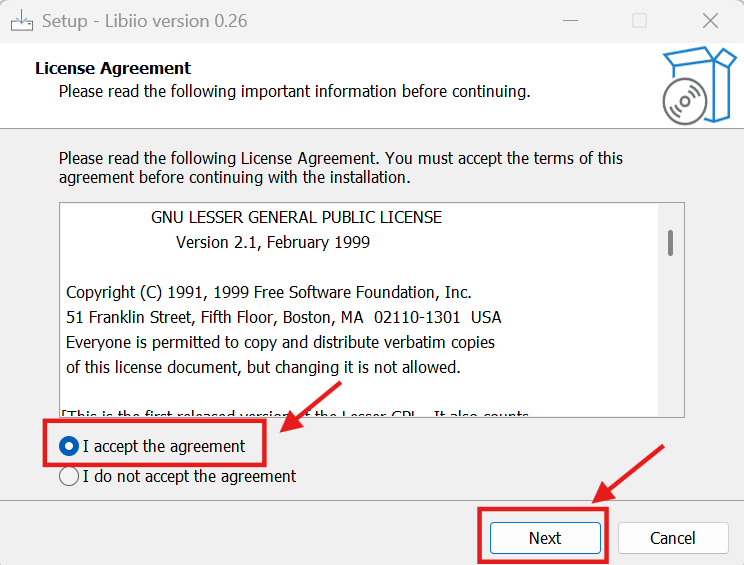
Click“Install”
Step 3: Verify successful installation
Open the Command Prompt (CMD) and enter:
iio_info -u ip:192.168.2.1
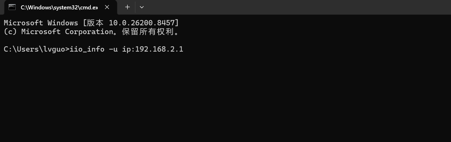
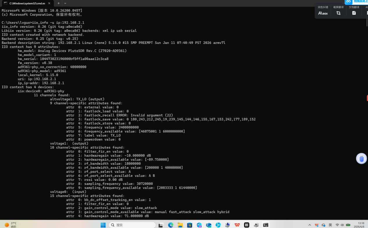
If the output shows the device information of PlutoSky R2 (such as ad9361-phy), it indicates that the communication is normal!
Note:
The USB driver must be installed first before libiio can find the device through the USB virtual bridge.
Before using iio_info for the first time, make sure the computer's IP address is set to 192.168.2.x.
Using network cable connection and required drivers
Step 1: Log in to PlutoSky R2 via the serial port (to gain control)
Since you are unable to log in via the network, you need to use the serial port for debugging.
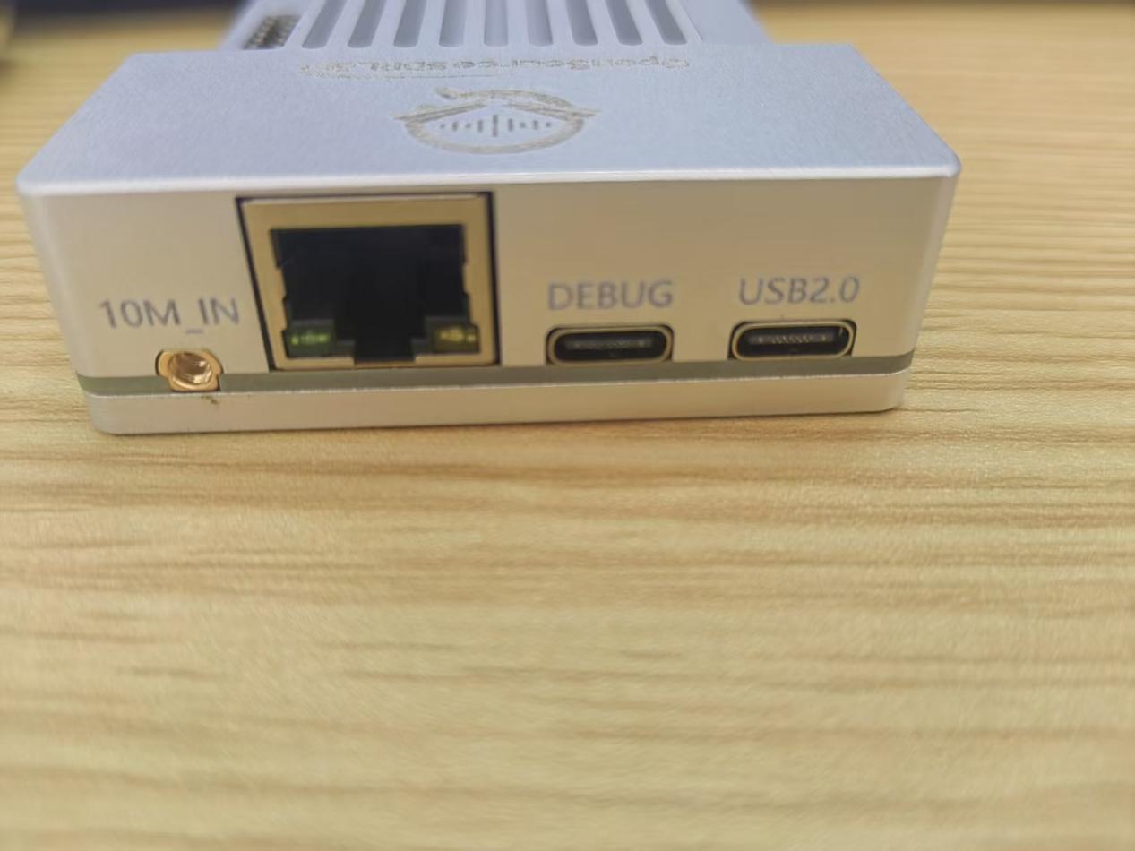
Prepare hardware: Connect the USB-C cable to the debug port (in the middle)
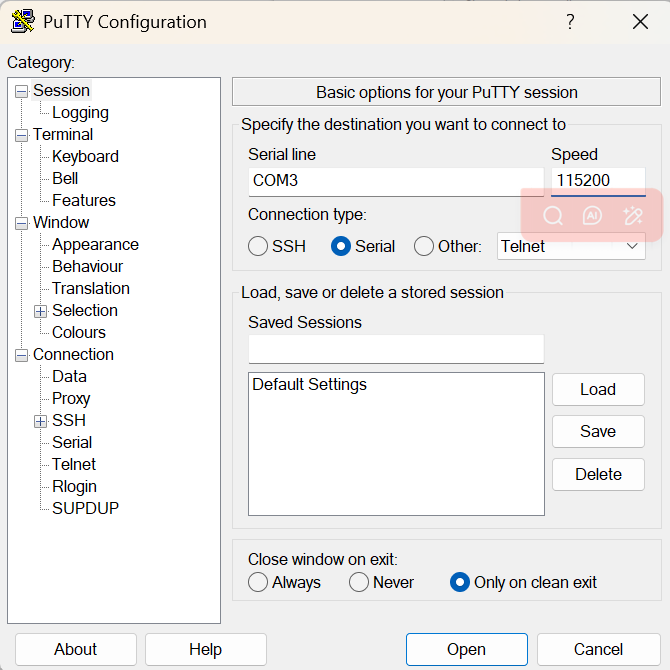
You need a software to act as the "terminal" for communicating with the serial port device. Here are some common options:
For Windows systems, use PuTTY or Tera Term.
On macOS/Linux systems, use screen or minicom.
Set the baud rate to 115200
Restart PlutoSky R2:
Power off and then power on again (or short-circuit the reset pin)
The serial port window will display the startup log (U-Boot → Linux)
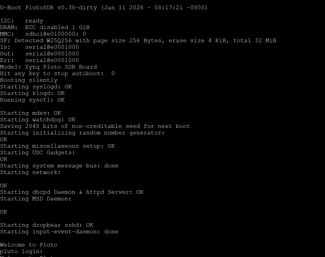
Log in to the system:
When "pluto login:" appears, enter:
Username: root
Password: analog
Step 2: Check the current network configuration
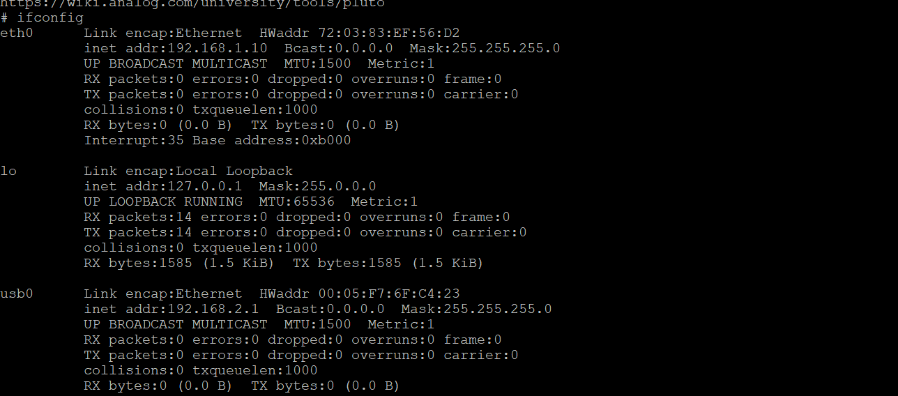
After logging in, enter the following command:
ifconfig
Or
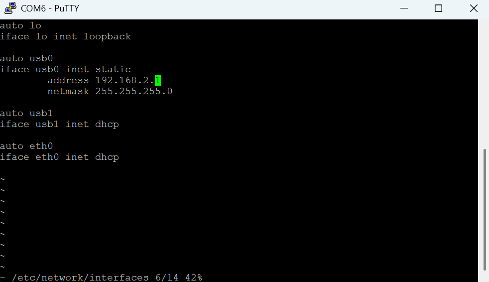
cat /etc/network/interfaces
You will see something similar:
Step 3: Temporary modification of IP
Suppose you want to change it to 192.168.6.10 and the gateway to 192.168.6.1, execute:
# Set IP and subnet mask
ifconfig eth0 192.168.6.10 netmask 255.255.255.0 up
# Set default gateway (optional, for accessing the external network)
route add default gw 192.168.6.1
Step 4: Test the new IP
On the computer, change the network card IP to the same subnet (such as 192.168.6.20), and then ping:
ping 192.168.6.10
If it works, it means success!
Permanently modify IP:
If you want the changes to remain effective after a reboot, you need to edit /etc/network/interfaces:
vi /etc/network/interfaces
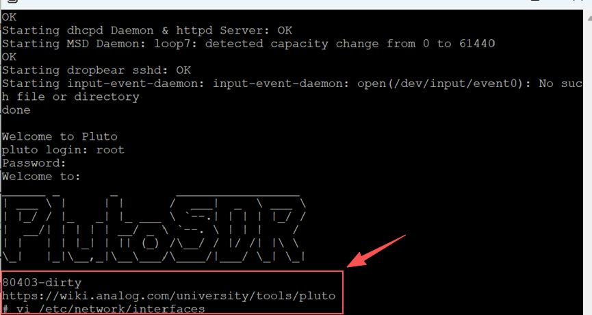
Modify the "address" field, save the changes and then restart.
PothosSDR Installation
The reason for recommending PothosSDR is that it can significantly simplify the setup of the development environment for PlutoSky R2. As a pre-compiled software package, it does not require manual compilation of underlying drivers and libraries such as libiio, SoapySDR, or gr-iio, avoiding complex dependency handling and compilation errors. It automatically integrates PlutoSky R2's dedicated support module (SoapyPlutoSDR) and provides a graphical device manager (PothosUtil) for connecting and debugging hardware, while being seamlessly compatible with popular SDR applications such as CubicSDR. Truly achieving out-of-the-box usability for PlutoSky R2, allowing developers to focus on signal processing and application development rather than environment configuration.
Download PothosSDR
You can obtain the driver in the following two ways:
1.The driver file is included in the resource package.
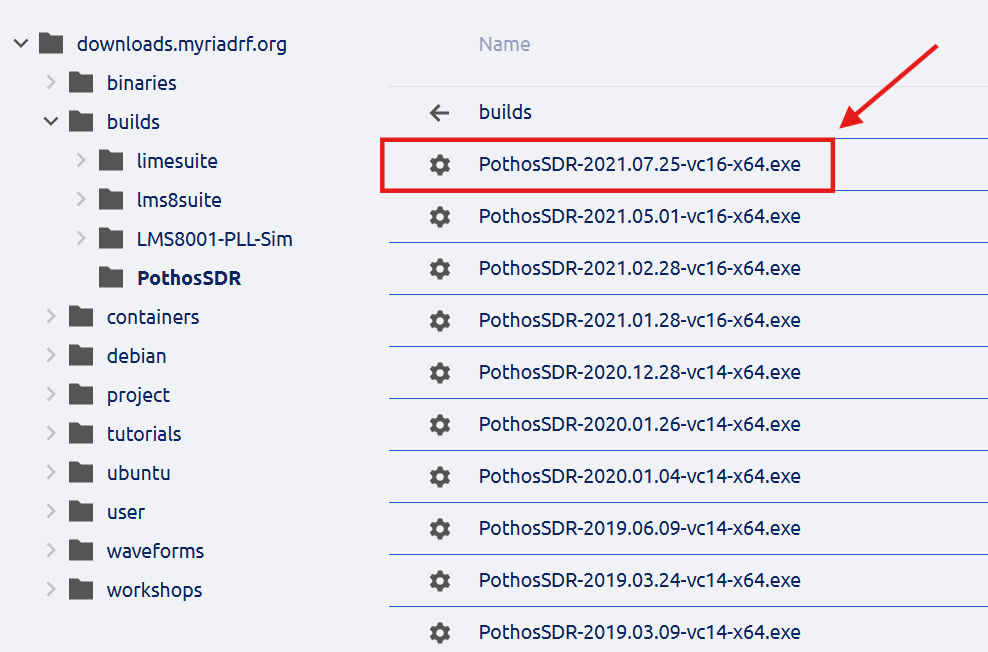
The file is located in the " Software Package " folder. The file name is: PothosSDR-2021.07.25-vc16-x64

2.Open your browser and visit the official release page of PothosSDR:
https://downloads.myriadrf.org/builds/PothosSDR/
Or
https://github.com/pothosware/PothosSDR/releases
Download the latest version of the Windows installation package (recommended 64-bit):
Such as:PothosSDR-2021.07.25-vc16-x64.exe
Install PothosSDR
Run the installation program as an administrator.
“Next”→“I accept”→“Next”
The installation path is recommended to be set to the default (such as C:\Program Files\PothosSDR).
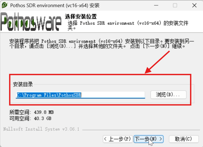
Wait for the installation to complete (approximately 2–5 minutes), and no restart is required.
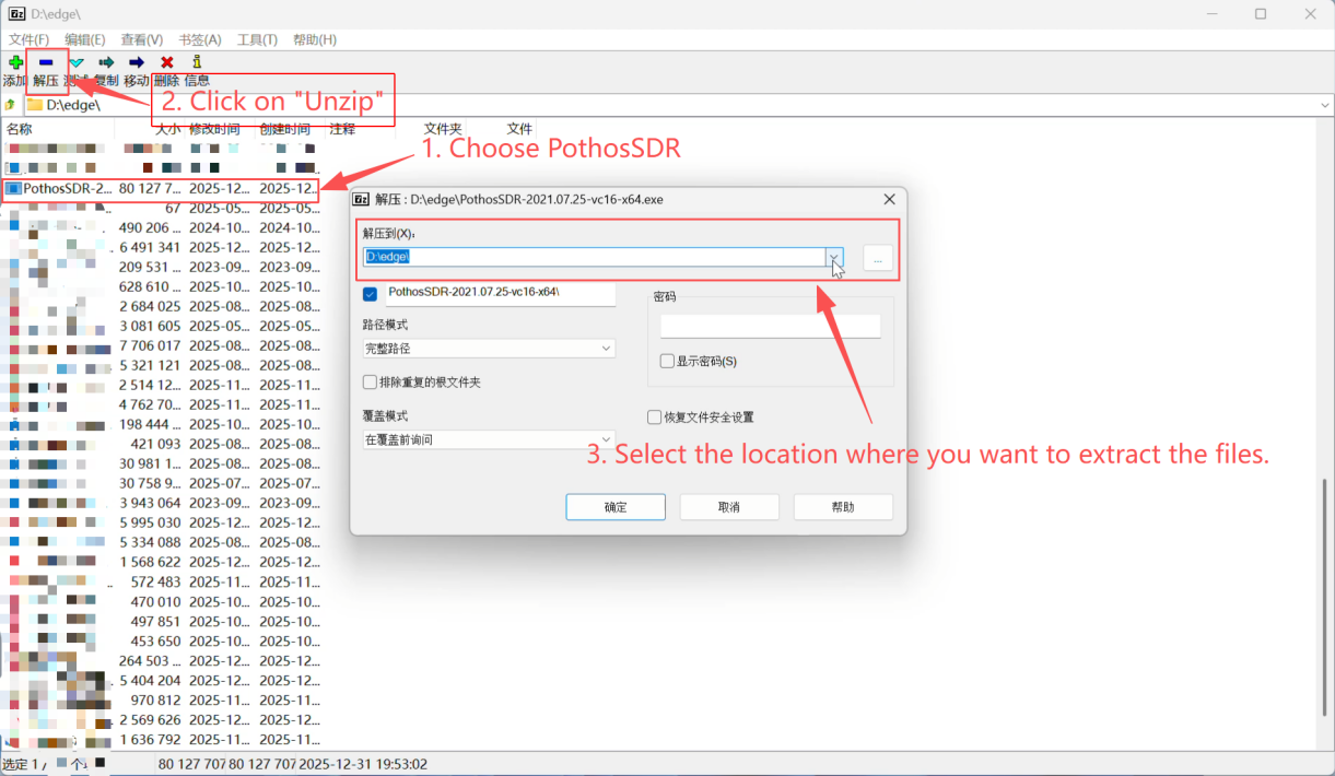
If there is a failure due to "path too long", you can try to remove the length restriction of the path, or directly open the installation program.exe file with a compression software and extract all the directories.
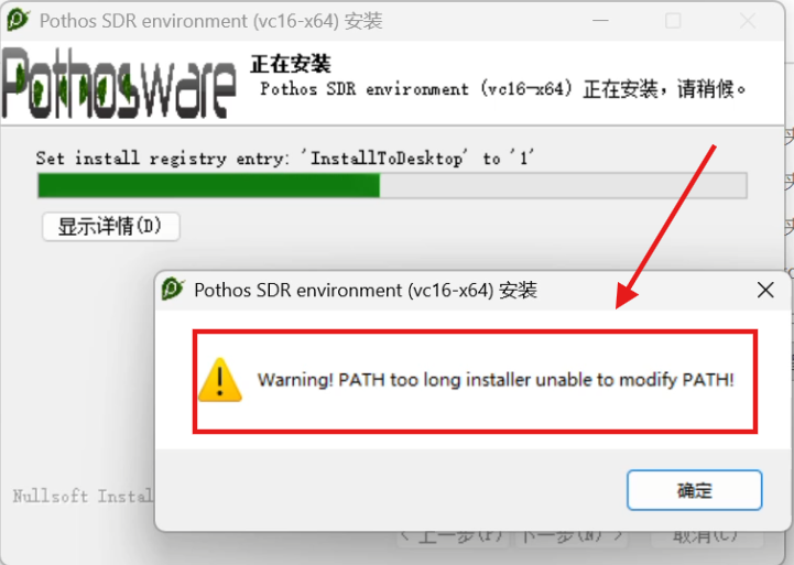
Here, we demonstrate how to solve the problem of an excessively long installation path using compression software (such as 7-zip).
Open your compression software (such as 7-zip)
Select PothosSDR-2021.07.25-vc16-x64.exe
Click the "Unzip" button
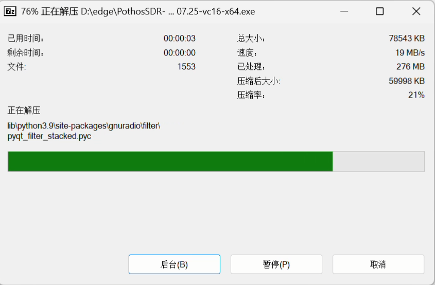
Just wait until the decompression is complete.
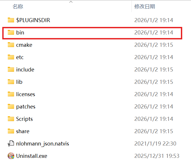
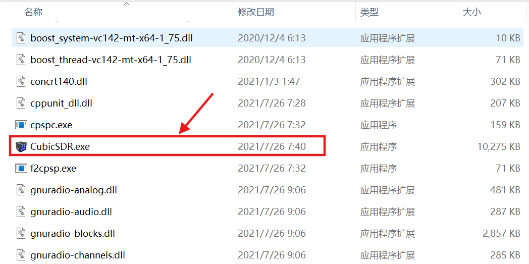
The CubicSDR software is located in the bin folder within the PothosSDR-2021.07.25-vc16-x64 folder.
PothosSDR will automatically register the relevant DLLs and plugins to the system path. When CubicSDR is launched, PlutoSky R2 support will be automatically loaded.
Installation and Use of CubicSDR
CubicSDR is an open-source, cross-platform, and powerful general-purpose software-defined radio (SDR) visualization tool that supports various SDR hardware, including PlutoSky R2. On the Windows platform, through the PothosSDR suite, all necessary dependencies (including drivers, libraries, and plugins) can be installed in one click, significantly simplifying the configuration process. This tutorial uses CubicSDR included in PothosSDR. Make sure to install PothosSDR first.
Method 1: Utilizing Ethernet Connection
Step 1: Connect PlutoSky R2 and confirm network connectivity
Premise: PlutoSky R2 has been connected to the computer via USB and the IP address has been configured (default 192.168.2.1).
If you have modified the IP of PlutoSky R2 to 192.168.6.10 as per the previous instructions, make sure the computer's network card is in the same network segment (such as 192.168.6.x).
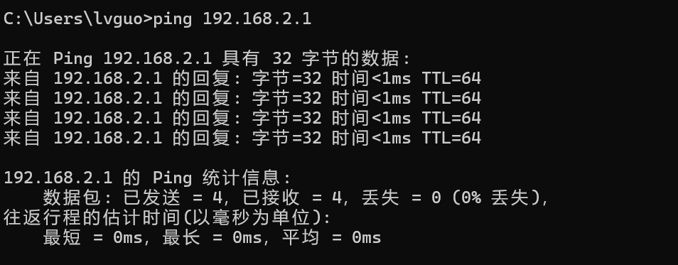
Open the Command Prompt (CMD) and test the connection:
ping 192.168.2.1 or ping 192.168.6.10
If you see "Reply from 192.168.X.XX", it indicates a smooth network connection.
(Optional) Verify if PlutoSky R2 is recognized by SoapySDR:
Open the Start menu → Search for "PothosUtil" and run it
Click on the "Device Manager" tab
Check if the plutosdr device is listed (you may need to click "Refresh")
Step 2: Start CubicSDR and add the PlutoSDR device
Open the Start menu, search for and launch CubicSDR.
When you first start it, a "Device Configuration" window will pop up.
If it doesn't appear, you can click the menu bar "View" → "Device Configuration" to open it manually.
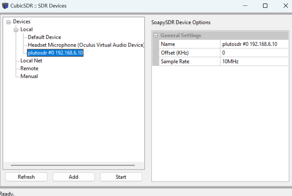
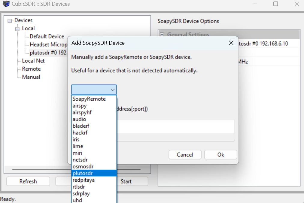
In the device list, click the " + Add" button at the lower left corner.
In the pop-up "Add Device" dialog box, fill in the following parameters:
driver=plutosdr, hostname=192.168.6.10
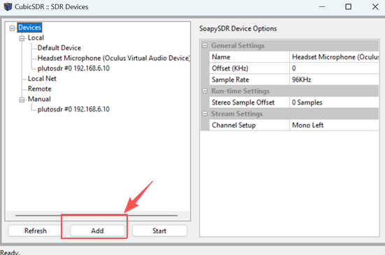
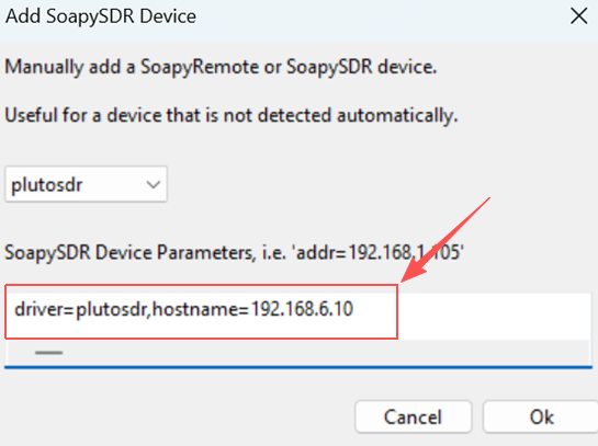
Driver fixed value, indicating the use of PlutoSDR driver
Hostname: Current IP address of PlutoSDR
CubicSDR will automatically fill in the default values Note:
Do not fill in http:// or port numbers
If using the default IP, this field should be filled with 192.168.2.1
Click "OK" to save
Return to the device list and you will see the newly added device, for example:
PlutoSDR #0 192.168.6.10
Select this device, click the bottom right "Apply" → "Close"
Method 2 (Recommended): Use a USB bridge for direct connection
Insert the USB cable into the USB port. If the driver is installed completely, the device can be correctly recognized in the Device Manager.
Start the CubicSDR located in the "bin" folder of the Pothos-SDR installation directory.
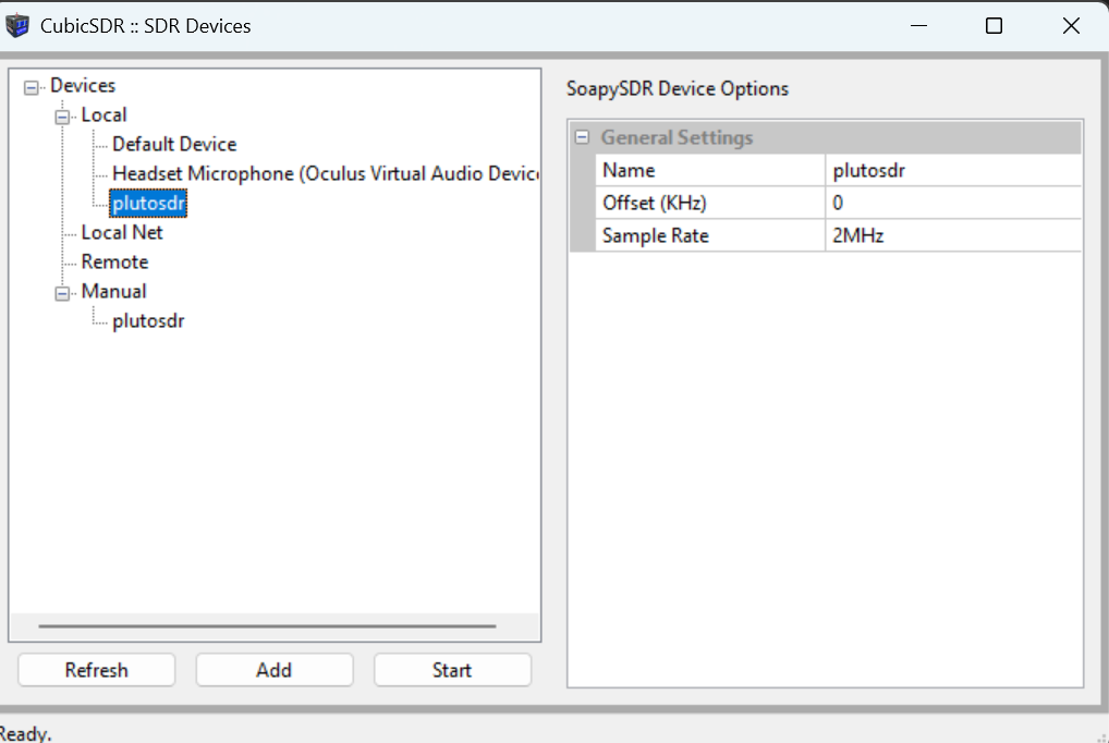
A default Plutosdr can be seen to appear. Click "start" to activate it.
If there are issues such as freezing or crashing, try unplugging and replugging the device or using an Ethernet connection.
Start using CubicSDR
The main interface of CubicSDR will automatically connect to PlutoSDR.Adjust the center frequency (e.g. 100 MHz) and bandwidth (e.g. 2 MHz).
You will see the real-time spectrum and waterfall graph.
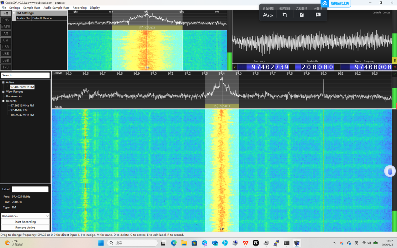
It can receive FM radio, aviation ADS-B, NOAA satellite images, etc. (depending on the antenna and frequency) Congratulations! You have successfully used PlutoSky R2 on Windows via CubicSDR!
SDRangel Installation and Usage
Download and install SDRangel
You can obtain the driver in the following two ways:
1.The driver file is included in the resource package.
The file is located in the " Software Package " folder. The file name is: sdrangel-7.23.0-win64.exe

2.Open your browser and visit the official release page of SDRangel:
https://github.com/f4exb/sdrangel/releases
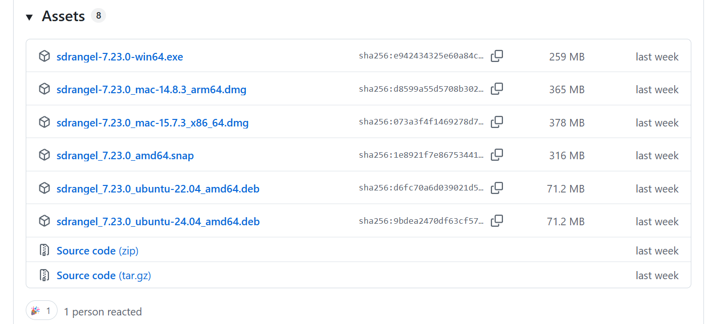
Note: For Windows, the PlutoSDR driver (from Analog Devices) needs to be installed separately; otherwise, the device cannot be recognized.
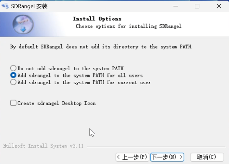
After the download is completed, double-click on sdrangel-7.23.0-win64.exe to run and start the installation.
“Next”→“I accept”→“Add sdrangel to the system PATH for all users”→“Next” →Select the location where you want to install. →“Install”
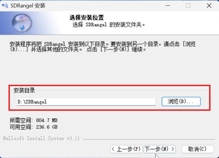
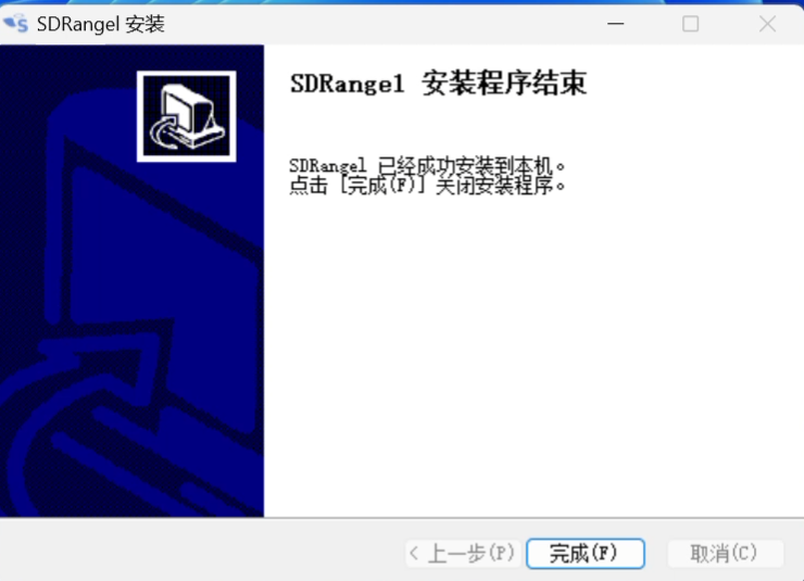
It will only take a few minutes for the installation to complete.
Configuring PlutoSDR and SDRangel
Step 1: Connect the device
Connect PlutoSky R2 via USB cable.
On Windows, the Device Manager should display "PlutoSDR".
Step 2: Start SDRangel
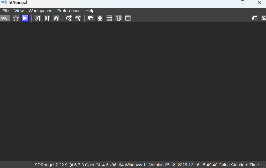
Open sdrangel and you will see a blank interface.
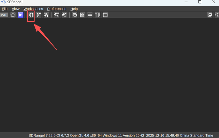
Make sure that the insertion device has been inserted and the driver installation has been completed. Click on this icon to add a new receiver.
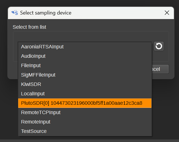
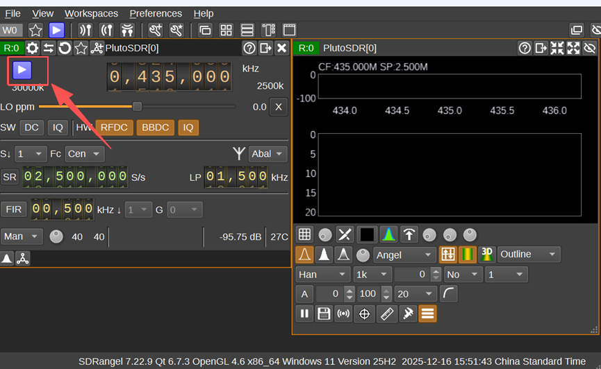
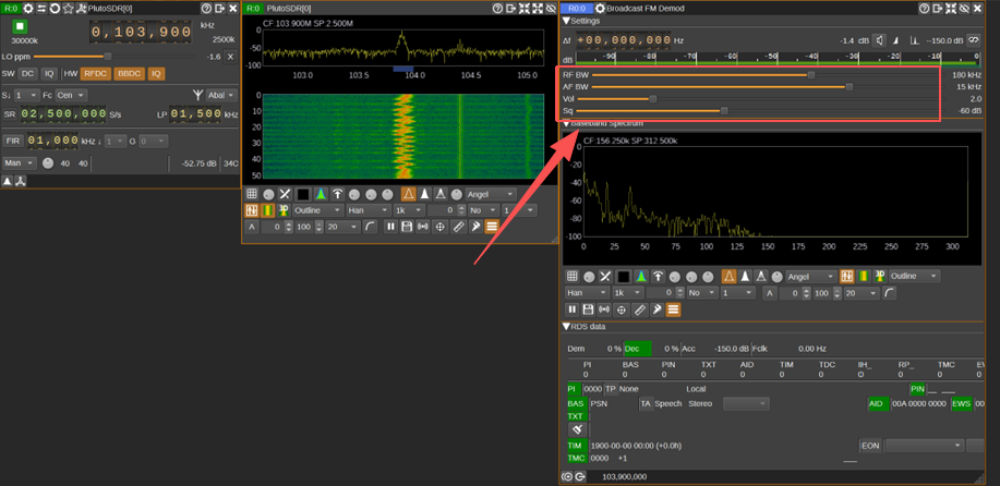
Select "PlutoSDR" in the pop-up box, then enter the receiving interface as shown in the figure. Click the purple triangle to start the receiving device.
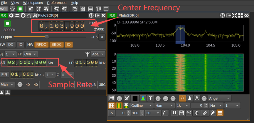
Sample Rate: It is recommended to set it to 2.4 Msps (the FM broadcast bandwidth is approximately 200 kHz, 2.4M is sufficient)
Center Frequency: Enter the FM frequency you want to listen to, for example 103.9 MHz
After starting, you can see the waterfall graph.
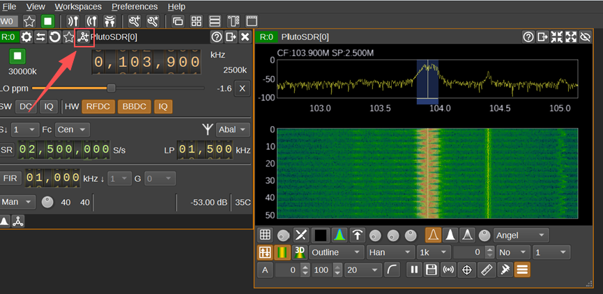
Click this button to add the demodulation channel.
In the "Demodulator Type" drop-down menu, select "Broadcast FM Demodulator"
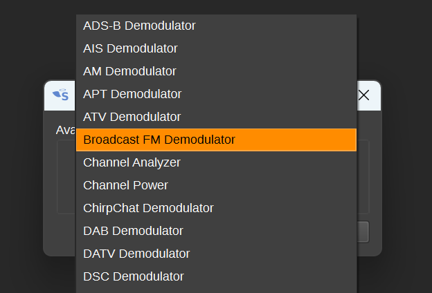
Adjust the parameters in the newly appeared window. Once it's done, you will be able to hear FM radio broadcasts.
Advanced Suggestions
Remote Reception: PlutoSky R2 supports network mode (default IP 192.168.2.1), and can be remotely controlled via http://pluto.local.
Multi-channel Monitoring: SDRangel supports running multiple demodulators simultaneously (such as FM + DMR), making full use of Pluto's 20 MHz bandwidth.
Automation Script: By combining Python + pyadi-iio library, automatic frequency scanning and recording can be achieved.
Universal Radio Hacker (URH) Installation and Usage
Download and Installation of URH
You can obtain the driver in the following two ways:
1.The driver file is included in the resource package.
The file is located in the " Software Package " folder. The file name is: Universal.Radio.Hacker-2.10.0-x64.exe

2.Open your browser and visit the official release page of URH:
https://github.com/jopohl/urh/releases
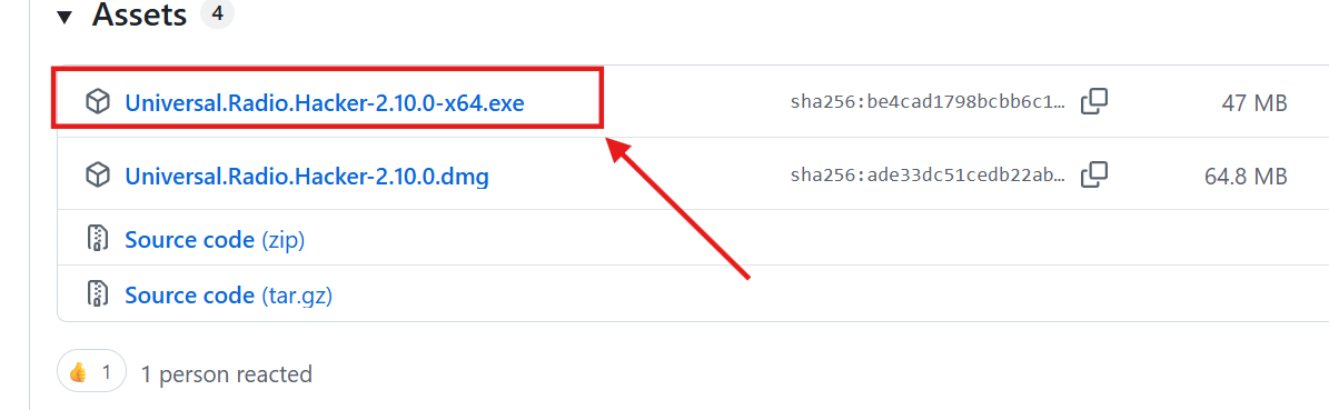
URH offers an official installation program on Windows, eliminating the need for manual configuration of the Python environment.
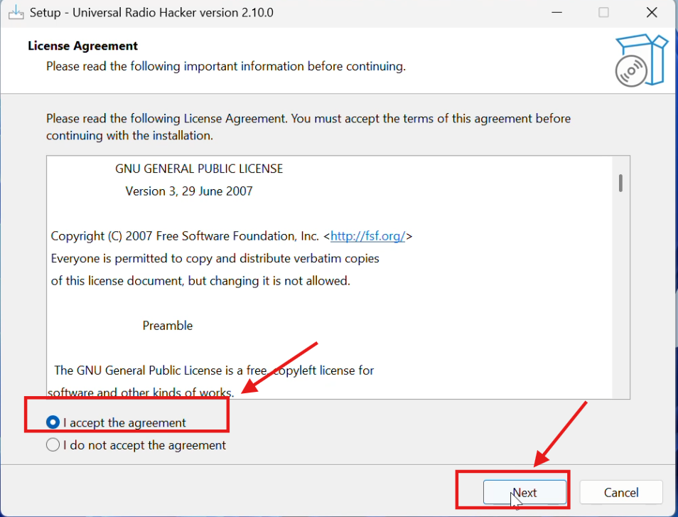
After the download is complete, double-click on Universal.Radio.Hacker-2.10.0-x64.exe to start the installation process.
“I accept the agreement”→“Next”→Select the installation location→“Next”
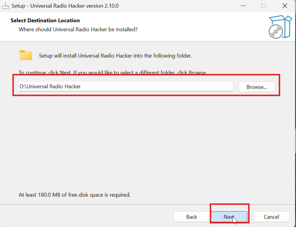
The official binary package includes all the dependencies (NUMPY, PYQT, SOAPYSDR, etc.) and avoids any environmental conflicts.
Using URH to record FM signals
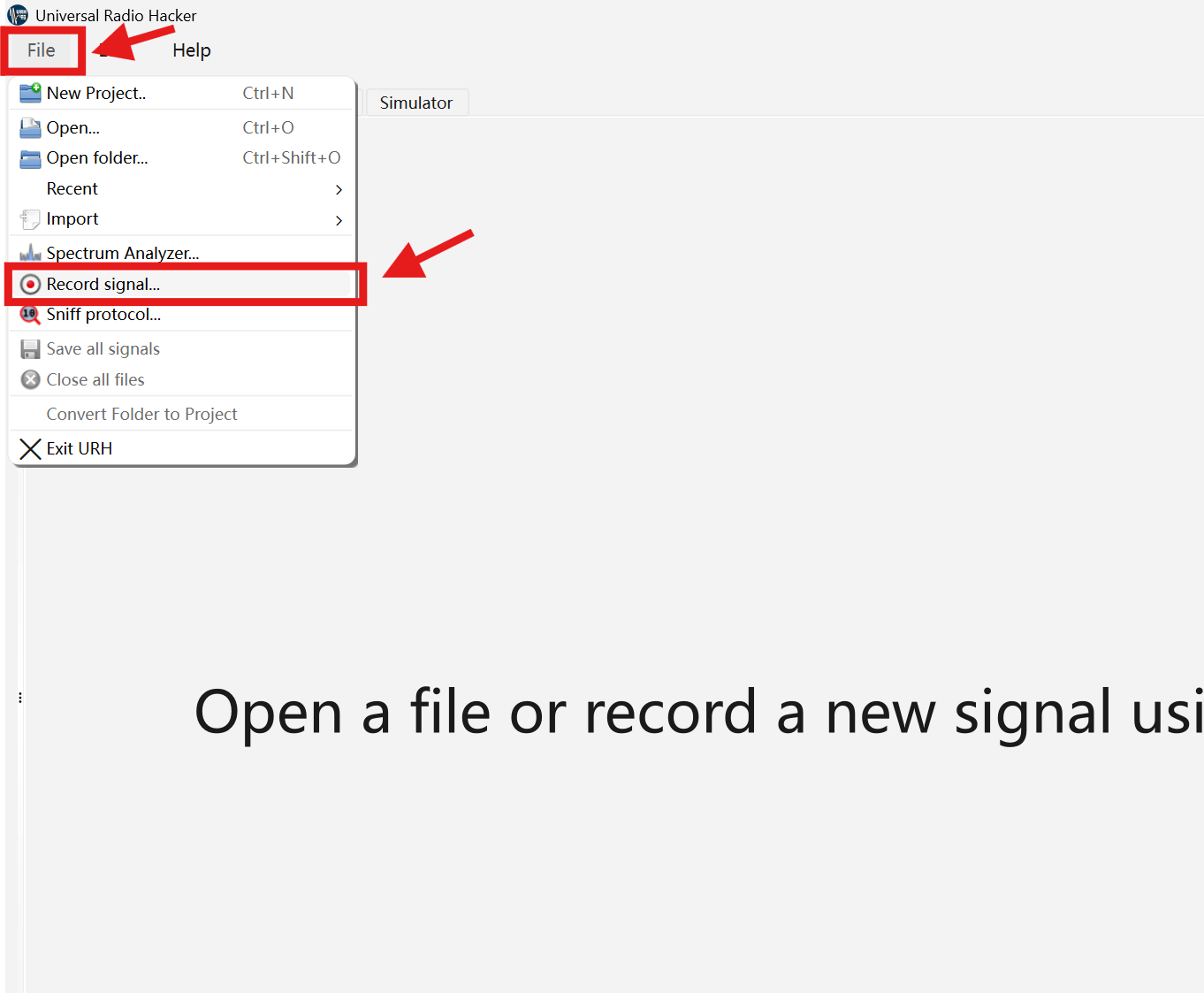
After starting the URH, click on the "File" button at the top of the main interface to find the red recording button (Record).
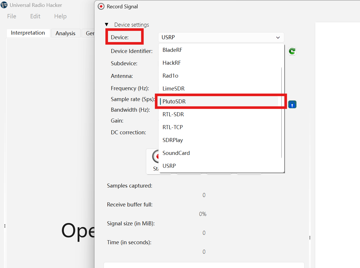
In the "Device" column, select PlutoSDR.
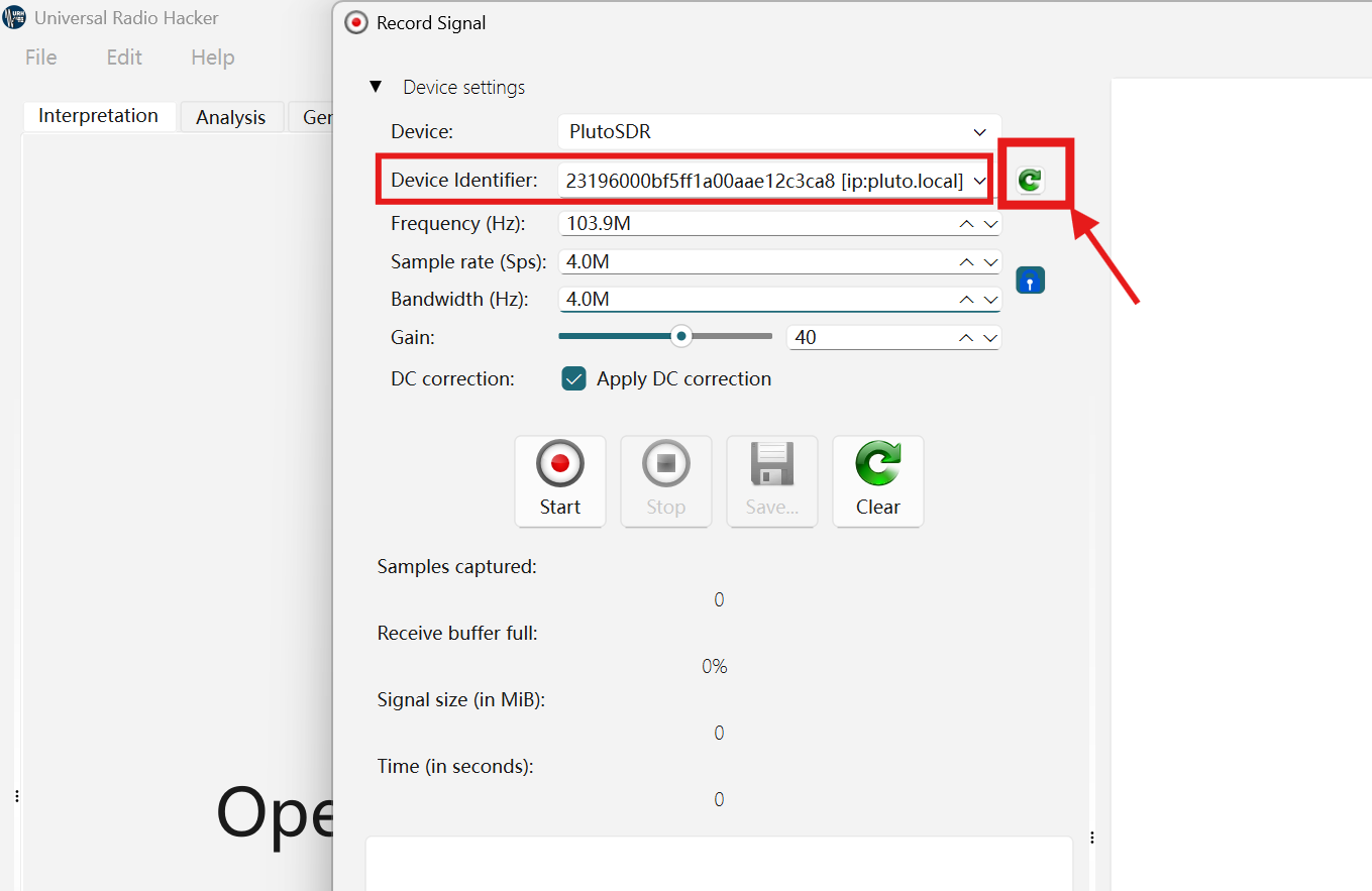
Click the green arrow to refresh the device.
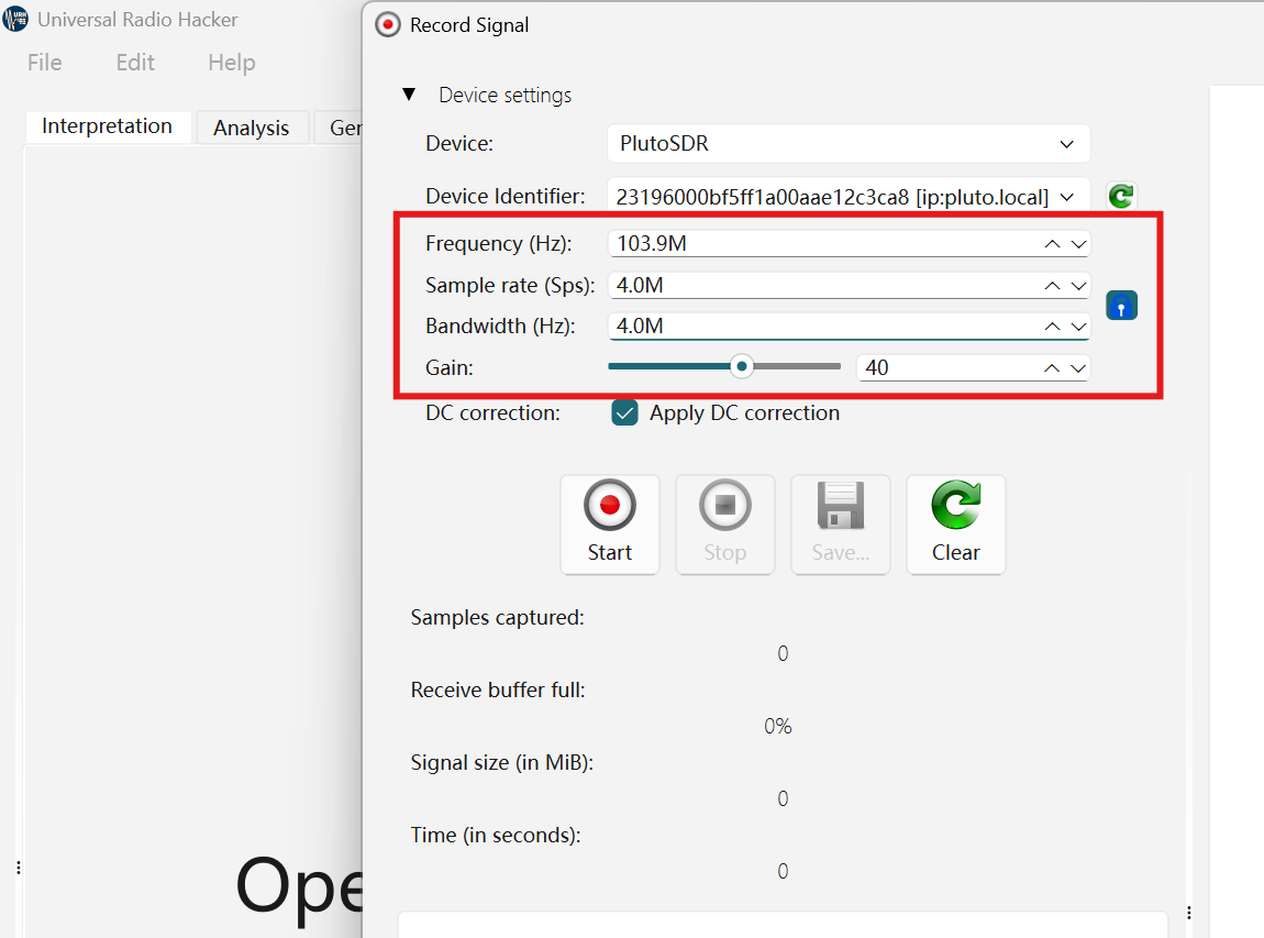
Set the parameters as follows:
Center frequency: e.g. 103.9 MHz
Bandwidth: 4 MHz (recommended for beginners)
Sampling rate: 2 MSPS
Gain: 40 dB (can be adjusted later)
Click "Start", and after 10 to 30 seconds of recording, click "Stop"
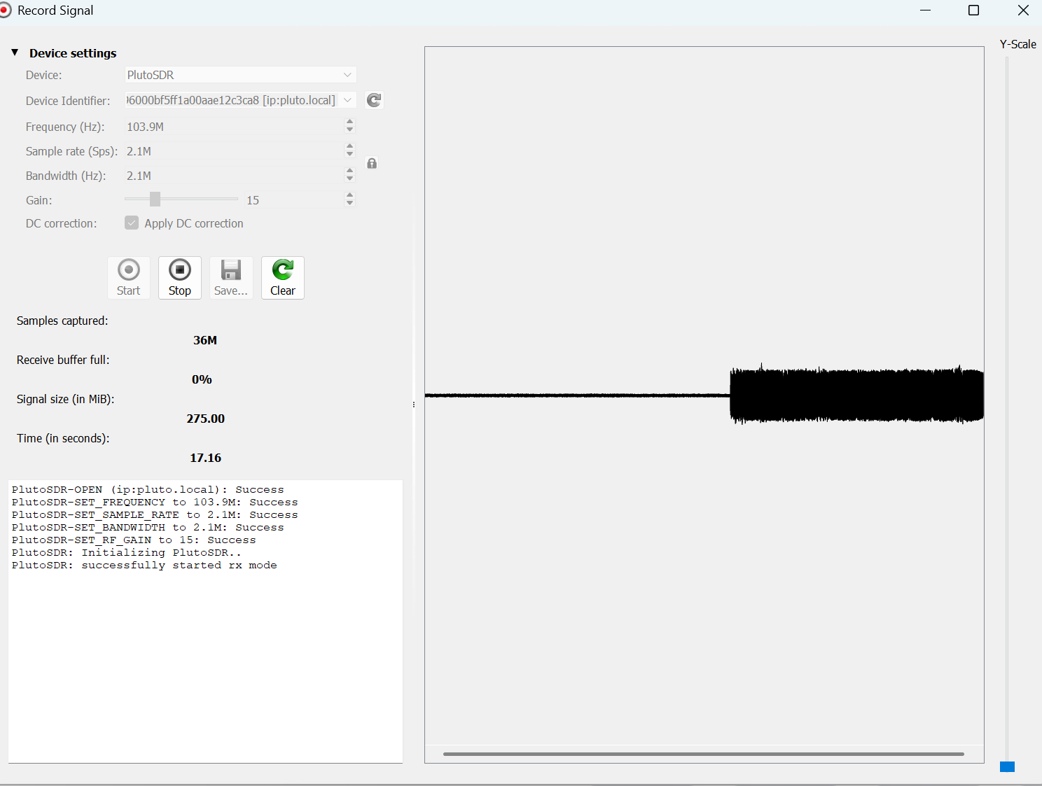
On the waveform interface, click "Save" to save the FM broadcast as a standard complex32s file, which can then be used for subsequent analysis or sharing.
Installation and Use of SDR Console
Download and install SDR Console v3
You can obtain the driver in the following two ways:
1. The driver file is included in the resource package.
The file is located in the " Software Package " folder. The file name is: SDR-Radio V3.3, 64-bit, 2024-02-05_0741.exe

2.Open your browser and visit the official release page of SDR Console:
https://www.sdr-radio.com/download
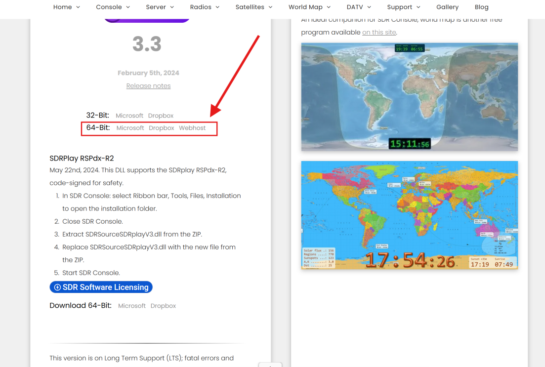
After installation, restart the computer (make sure the drivers and network stack are correctly loaded).
Configure PlutoSDR to SDR Console
Open SDR Console v3.
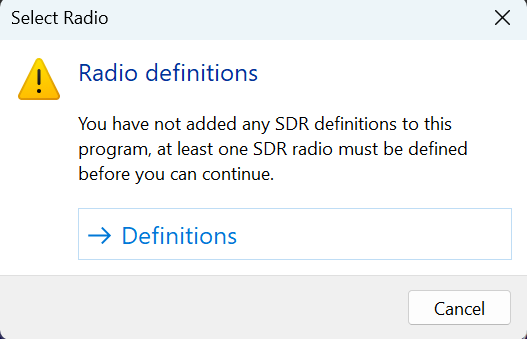
Enter "Radio Definitions" (it will pop up automatically on the first startup).
Click “Definitions”
Click on "Add" → Select "PlutoSDR"
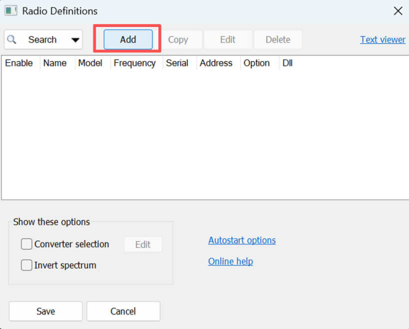
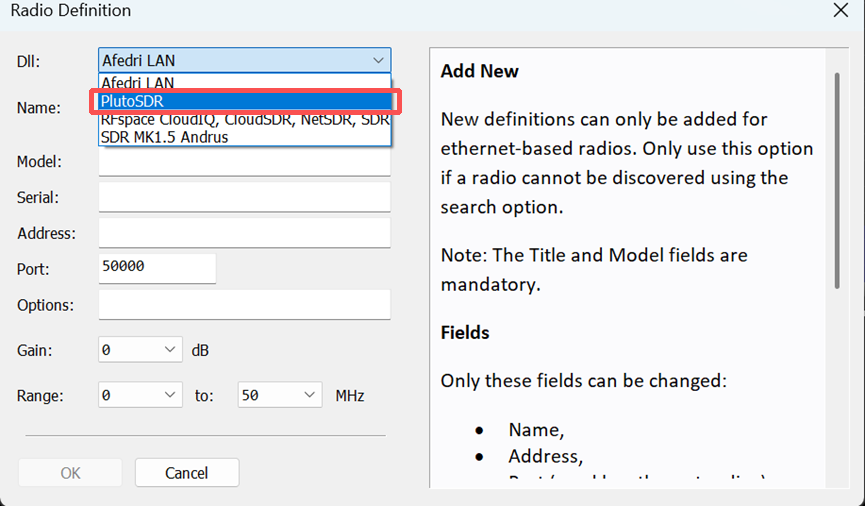
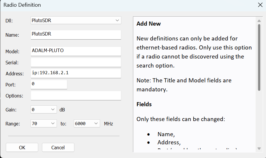
Enter connection information (you can also use the default parameters):
IP Address: 192.168.2.1
Port: 5110 (default IIO port)
Bandwidth: 20 MHz (recommended for FM reception)
Sample Rate: 2.4 MSPS (balance performance and bandwidth)
Click "OK"
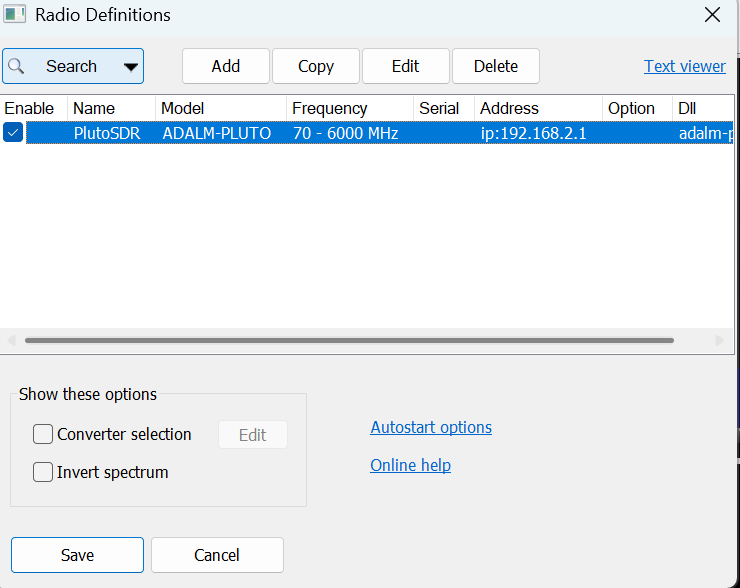
Select PlutoSDR, and then click "Save"
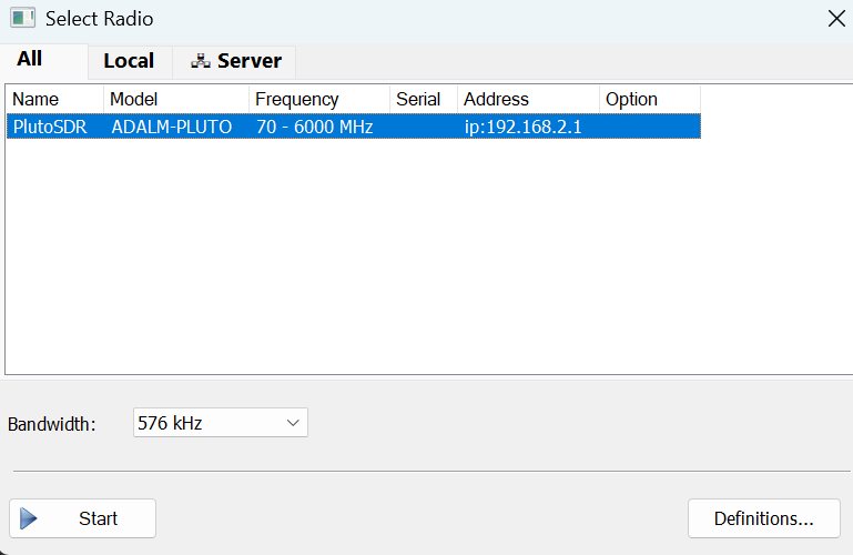
Click "start" and then close. The first time you use it, it might take a while to load, but it won't affect the normal connection.
Note: If the connection fails, please check if the Windows Firewall is blocking SDR CONSOLE's access to the local network.
Receiving FM Broadcasting via SDR Console
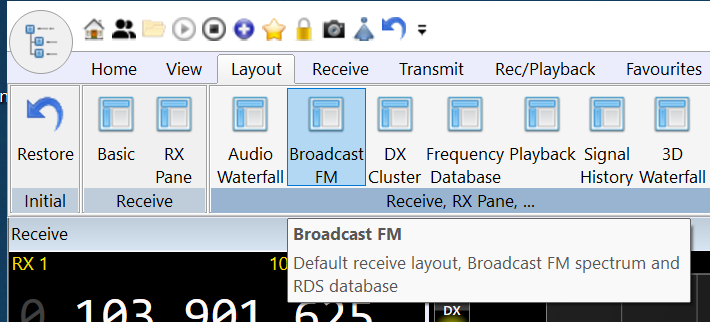
Start the SDR Console, then click "Layout" on the main interface → Select "Broadcast" or choose the function you need.
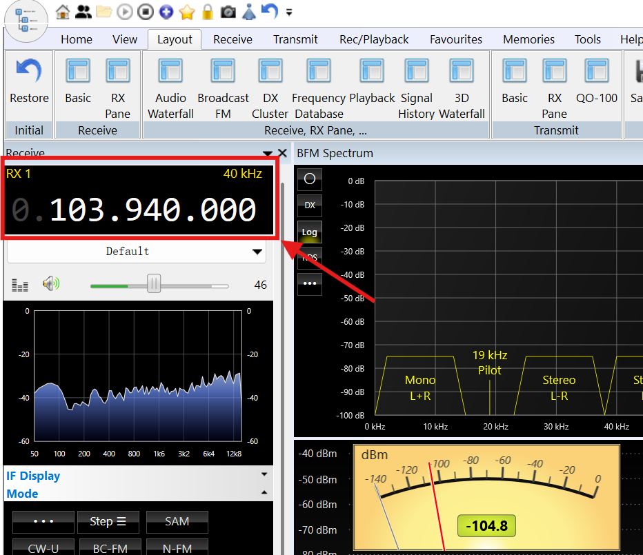
Enter the local FM frequency (such as 103.9 MHz) in the frequency column.
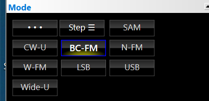
Mode selection: "BC-FM" (or WFM)
Adjust the following parameters to optimize the sound quality: Filter BW: 150–180 kHz
Squelch: Turn off (FM broadcasting usually doesn't require noise suppression)
AGC: Enable (Automatic Gain Control)
Connect headphones or speakers, and you can listen!
The SDR Console has an RDS decoder built-in, which can display the station name (requires a strong signal).
Advanced Techniques
Remote Use: PlutoSky R2 supports remote control via the network. Just set up port forwarding (5110) on the router, and you can use the SDR Console to receive signals from the external network.
Multiple Virtual Receivers: SDR Console supports opening multiple receiving channels simultaneously, allowing you to listen to multiple FM radio stations at the same time.
Spectrum Recording: Use the "Record" function to save IQ or audio for later analysis.
GNURadio Usage
Important prerequisite!!
This tutorial uses GNU Radio included in PothosSDR. Make sure to install PothosSDR first.
If it has not been installed yet, please complete the "2.3 PothosSDR Installation" section mentioned above.
GNU Radio is a powerful open-source signal processing framework widely used in SDR application development. Through its graphical interface GNU Radio Companion (GRC), users can build complex wireless communication systems without writing code. This section will guide you to quickly build an FM radio receiver based on PlutoSky R2 using GRC.
Start GNU Radio Companion
After installing PothosSDR, search for:
"GNU Radio Companion" or "gnuradio-companion" in the Windows Start menu.
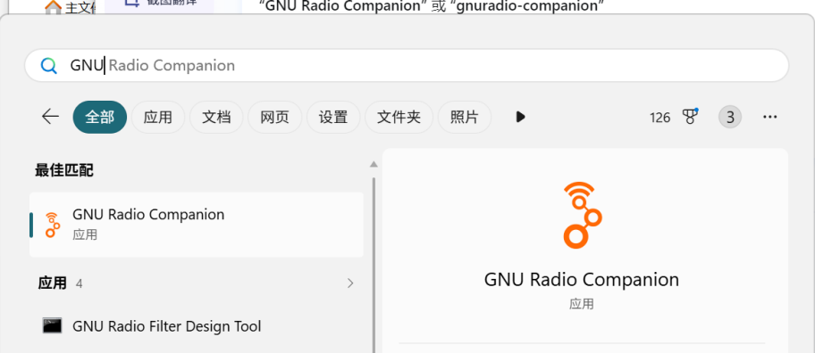
Or directly open GNU Radio Companion in the bin directory of PothosSDR.
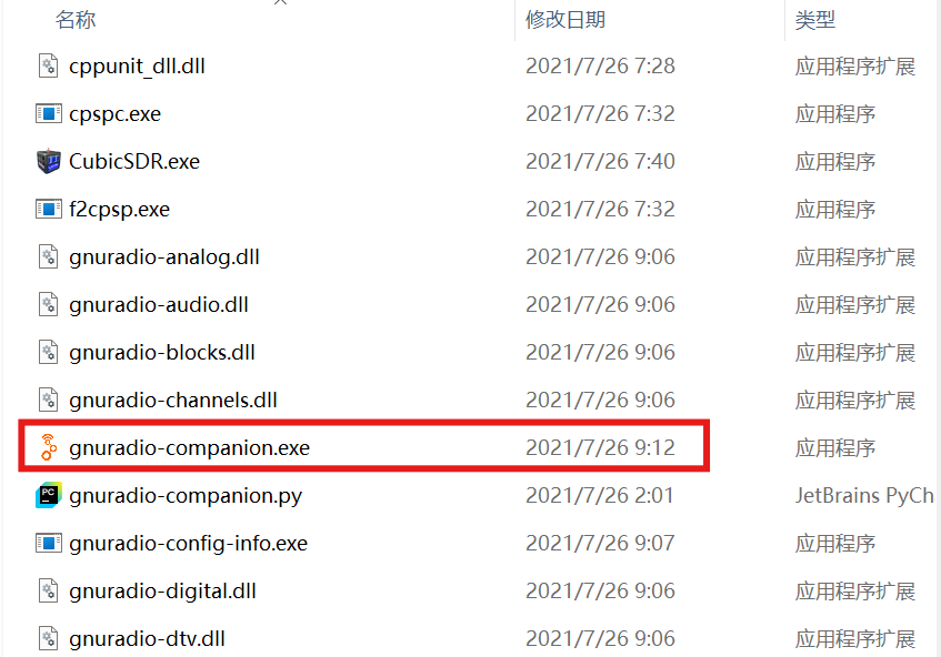
Run as an ordinary user (no need for administrator privileges).
The first startup might be a little slow (requiring module loading), please be patient and wait.
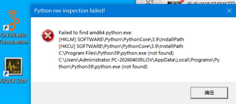
If the error shown in the diagram occurs, please install the matching version of Python 3.9 (64-bit).The corresponding version must be installed:
https://www.python.org/downloads/release/python-3913/
Verify whether the support for PlutoSky R2 has been integrated
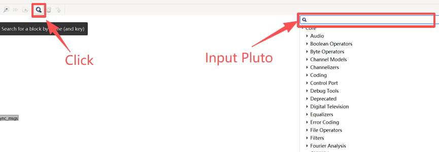
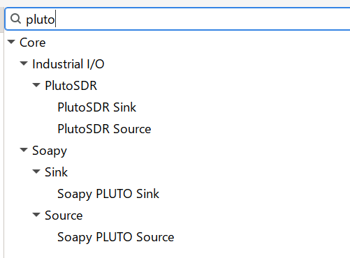
In the "Blocks" panel on the left side of the GRC interface, search for "Pluto".
If you see the "PlutoSDR Source" module, it indicates that the SoapyPlutoSDR plugin has been correctly loaded.
Creating FM Reception Flow Diagram Using GNU
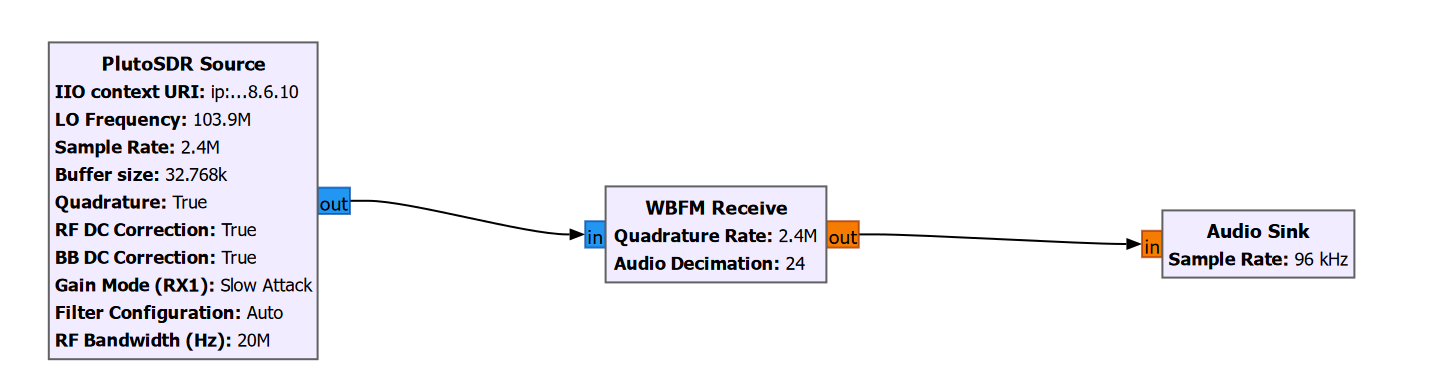
We will construct a classic FM receiving chain:
Step 1: Add the PlutoSDR signal source
From the left module list, drag "PlutoSDR Source" (located under the "Sources" category) onto the canvas.
Double-click on this module and configure the following parameters:
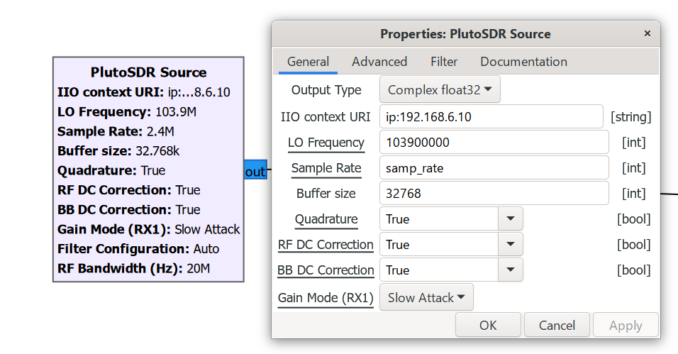
The FM radio frequency band usually ranges from 88 to 108 MHz. Please select the appropriate frequency based on your location.
Step 2: Add FM demodulator and audio output
After adding the module, set the parameters as follows:
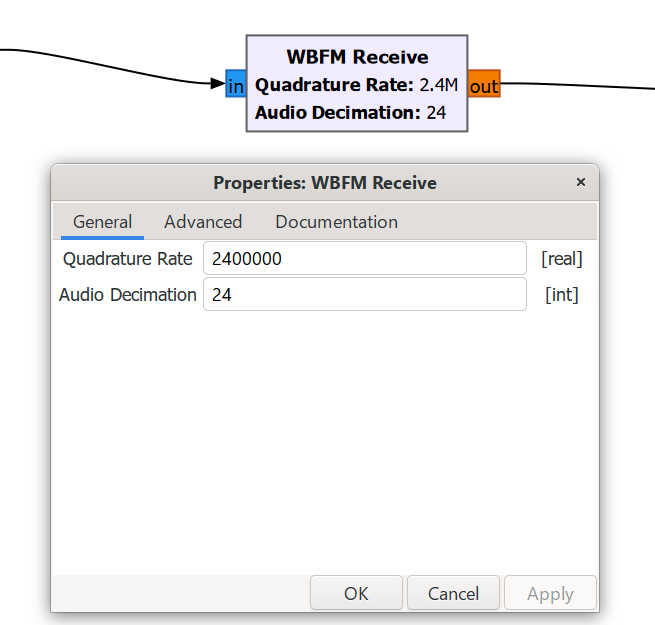
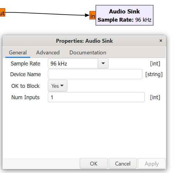
Ensure the global sample rate variable matches the hardware parameters.
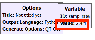
Step 3: Connect all the modules
Click on the output port of a module (the small dot on the right), and drag it to the input port of the next module (the small dot on the left).
After the connection is successful, a black line with an arrow will appear.
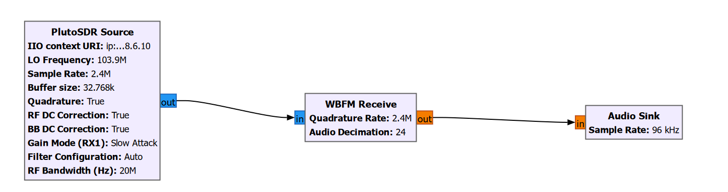
Save and Run the Flowchart
Click the menu bar "File" → "Save As", and save as "pluto_fm_rx.grc".
Click the "Play" button on the toolbar to run the flowchart.
When you run it for the first time, GRC will automatically compile the Python code and start.
Wait for a few seconds, and you should be able to hear the FM radio sound from your computer speakers!
Conducting Loopback Testing Using GNU
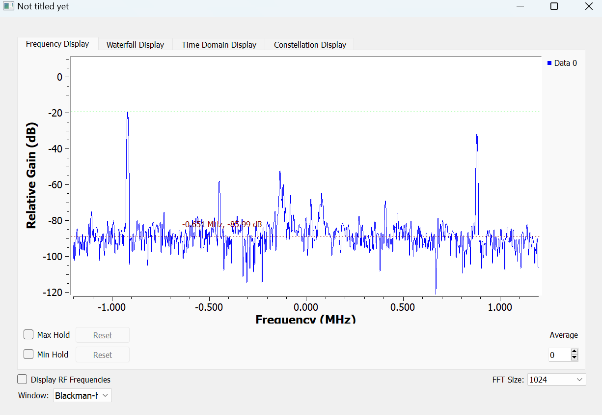
Build the following flowchart in GNU Radio. Install antennas on TX1 and RX1, and then click the "Start Running" button.
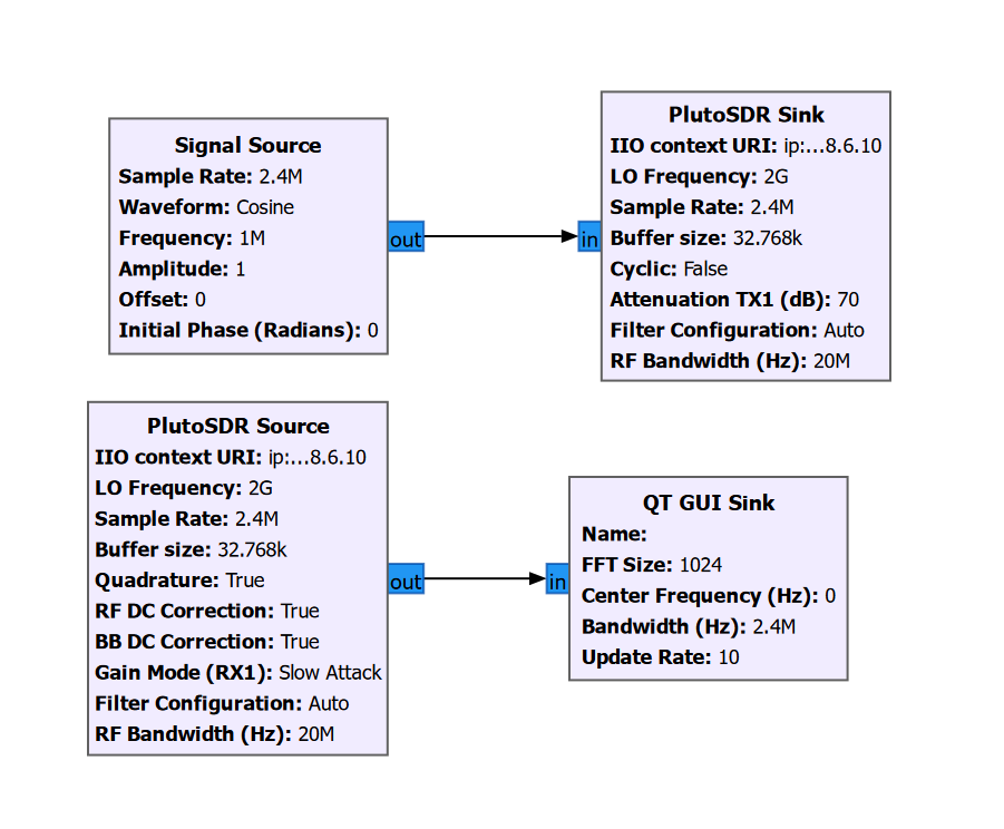
If you can observe the following spectrum graph, it indicates that the transmission and reception have been successfully carried out.
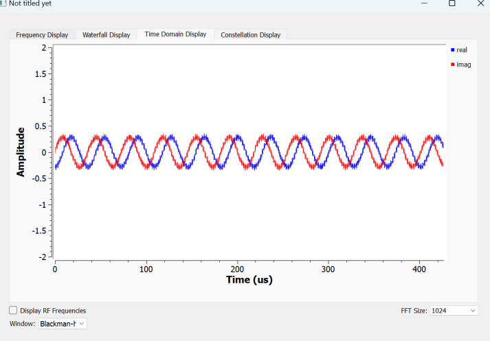
Testing the cracking result of the AD936X chip
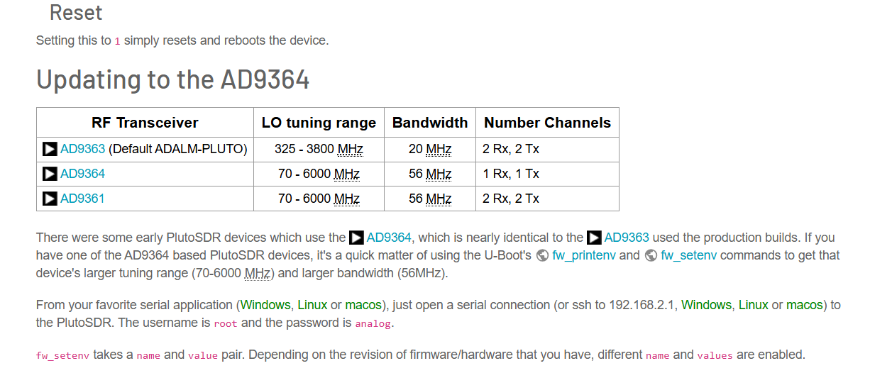
Use SDRSharp or other signal receiving software to test whether the equipment supports 70 MHz - 6 GHz.
The equipment itself is an AD9363 chip, but it has been cracked through software means and transformed into AD9361.
https://wiki.analog.com/university/tools/pluto/users/customizing
Here, CubicSDR is used for the demonstration.
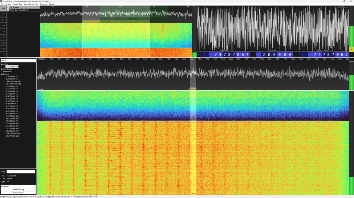
It can be observed that when the center frequency is adjusted beyond 70 MHz, the spectrum graph undergoes changes.
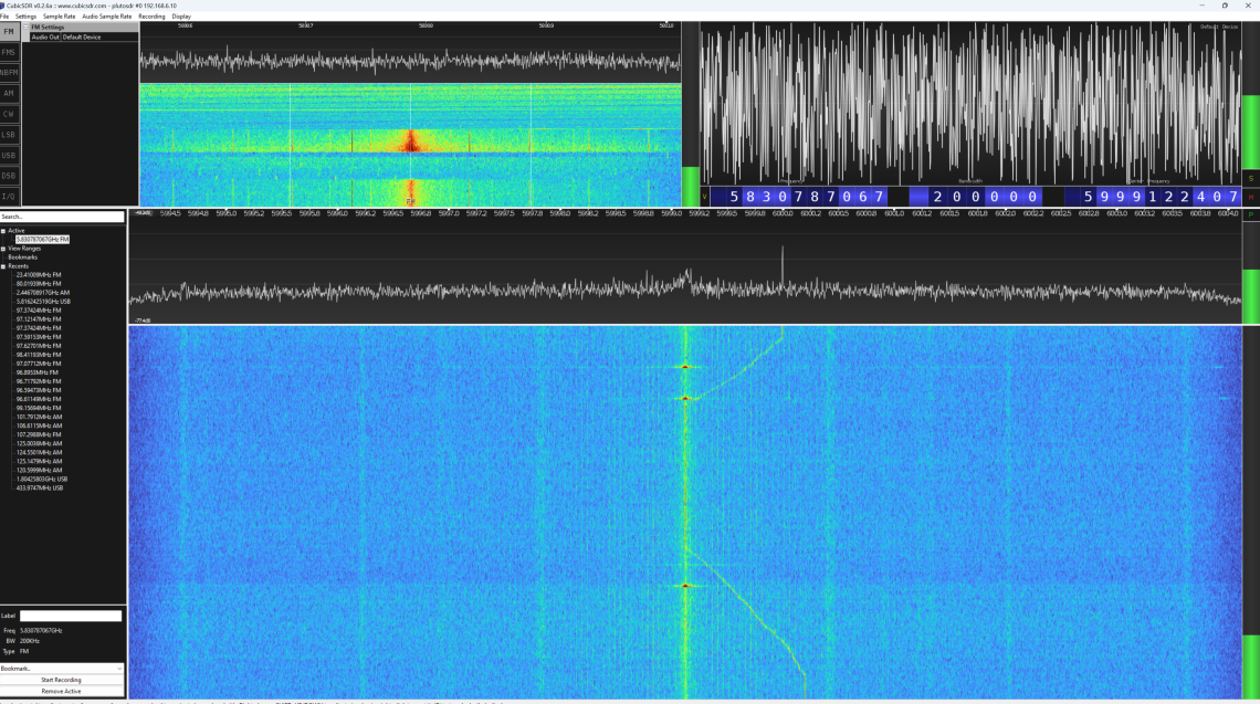
Moving slowly near 6G, it can be observed that when the center frequency exceeds 6000 MHz, the translation does not exhibit spectral characteristics, indicating that the device has the capability to receive 70 MHz - 6 GHz.
Ubuntu System Usage Tutorial
PlutoSky R2 Windows User Manual Youtube Video
This section covers driver installation and basic dependency libraries for PlutoSky R2 devices.
Install Ubuntu Drivers & Base Dependencies
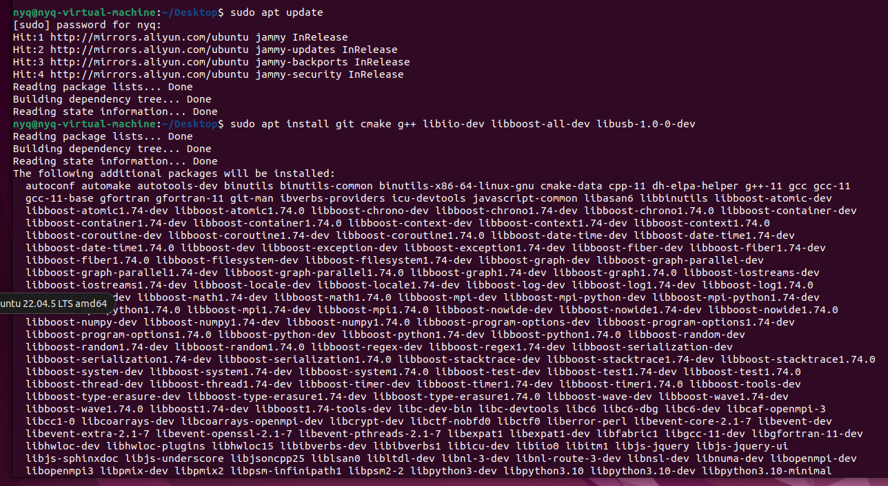
Open a terminal, update the package list, and install required tools and libraries.
sudo apt update
sudo apt install git cmake g++ libiio-dev libboost-all-dev libusb-1.0-0-dev
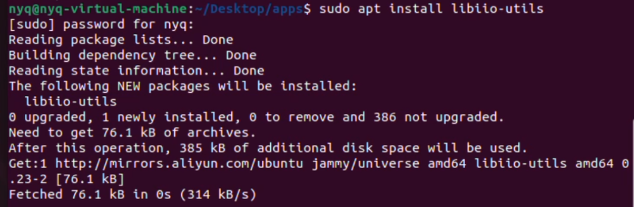
sudo apt install libiio-utils
Allow a few minutes for the process to complete.
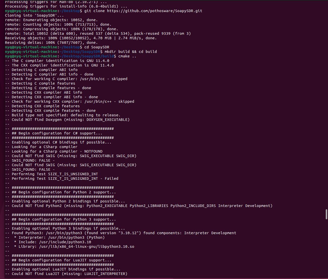
Then clone SoapySDR from GitHub, build and install it.
git clone https://github.com/pothosware/SoapySDR.git
cd SoapySDR
mkdir build && cd build
cmake ..
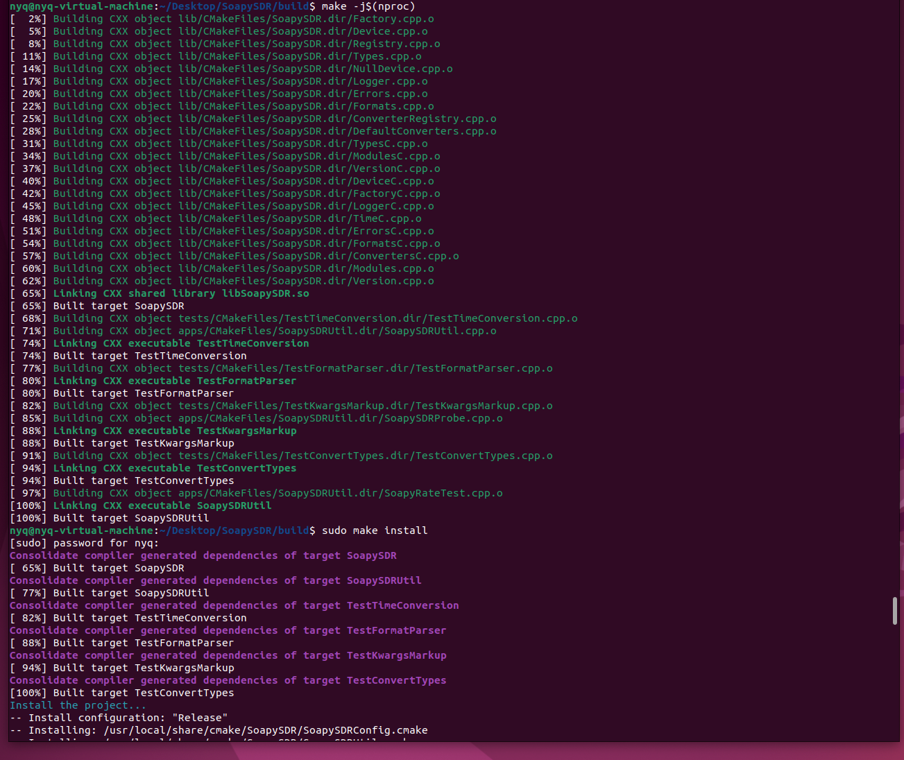
make -j$(nproc)
sudo make install
Enter the following command to update the dynamic library cache:
sudo ldconfig
SoapySDRUtil -info
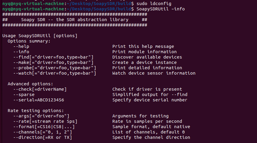
After success, the SoapySDR version and the plugin path will be displayed.
Install SoapyPlutoSDR Plugin & Verify Device
Enter the following command to return to the parent directory:
cd ../..
Clone and compile the SoapyPlutoSDR module.
git clone https://github.com/pothosware/SoapyPlutoSDR.git
cd SoapyPlutoSDR
mkdir build && cd build
cmake ..
make -j$(nproc)
sudo make install
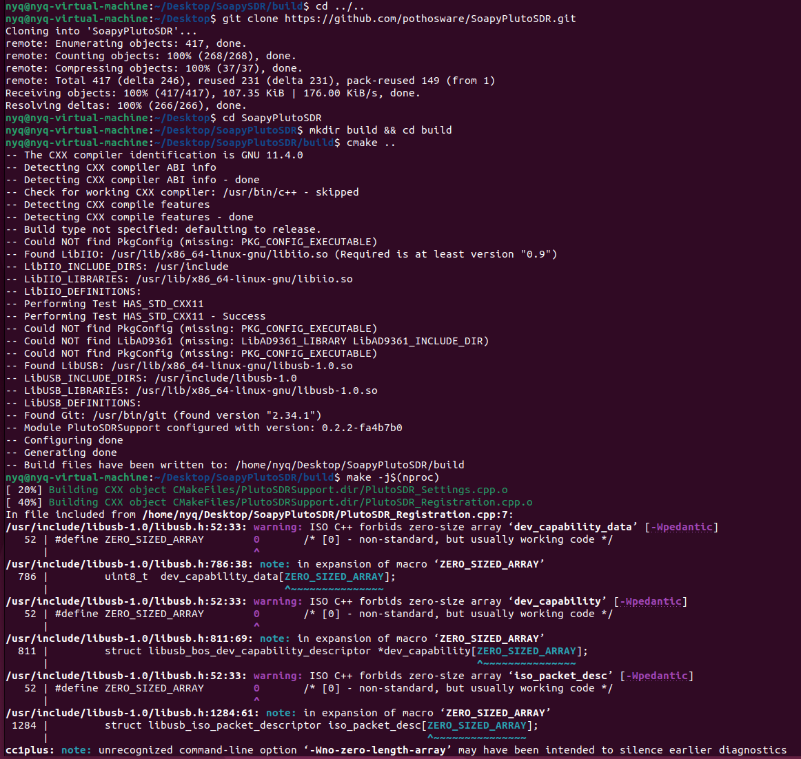
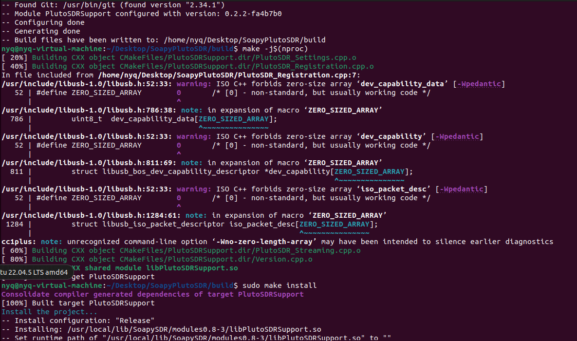
Finally, perform connectivity verification and hardware detection for the PlutoSky R1 device.
PlutoSky R2 Connectivity and Device Detection
ping -c 3 192.168.2.1

Read PlutoSky R2 hardware device information
iio_info -u ip:192.168.2.1 | head -n 40
s
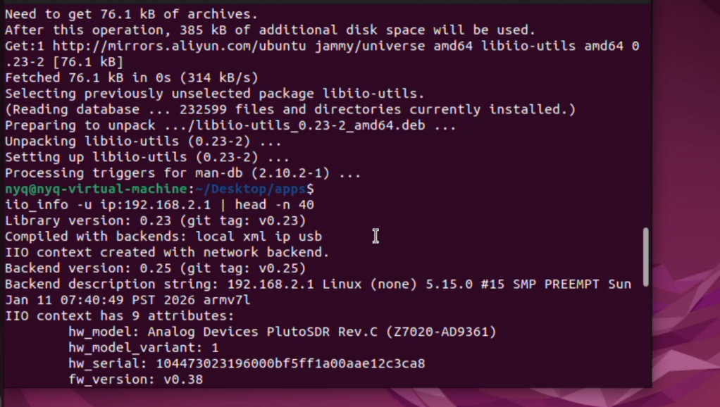
Probe PlutoSDR Soapy driver status
SoapySDRUtil --probe="driver=plutosdr,hostname=192.168.2.1"
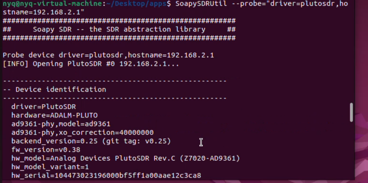
If you see PlutoSDR information, the driver is ready.
Install SDRangel
On Ubuntu, it is recommended to install SDRangel via snap.
sudo snap install core
sudo snap install sdrangel

The Snap version of SDRangel runs with restricted permissions by default. Without proper permissions granted, it will fail to detect USB devices, manage networks, access hardware information, record audio or demodulate signals. Please run the following commands to complete the configuration.
For the Snap version, run the following commands first to enable this feature:
sudo snap connect sdrangel:raw-usb
sudo snap connect sdrangel:avahi-control
sudo snap connect sdrangel:network-manager
sudo snap connect sdrangel:hardware-observe

If you encounter dependency issues, run:
sudo apt -fix-broken install
Launch SDRangel:
Sdrangel
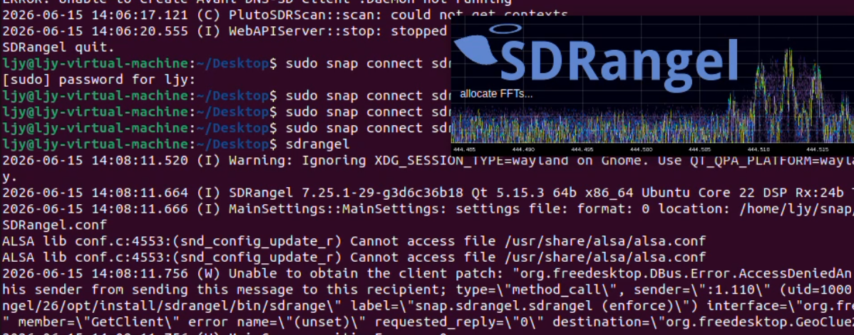
Using SDRangel to receive FM radio broadcasts
Firs,we need to connect the device to the computer via a USB cable,connect the antenna to RX1.
Once SDRangel is open, add a receiver and select “PlutoSDR”.
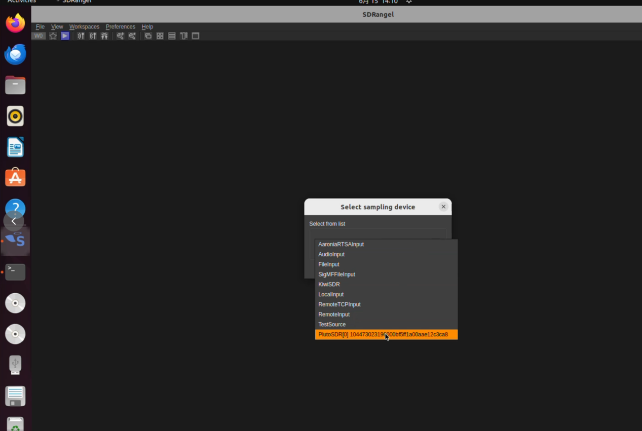
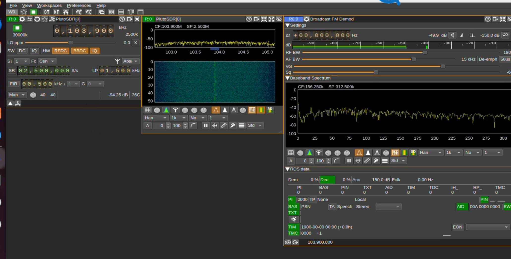
Set the center frequency to your local FM station (e.g., 103.9 MHz) and sample rate to 2.5 MHz.
Click the purple triangle to start reception.
In the “Channel” area, click “+” and add a “Broadcast FM Demodulator”.
Adjust the volume and you should hear the broadcast.
Install Gqrx
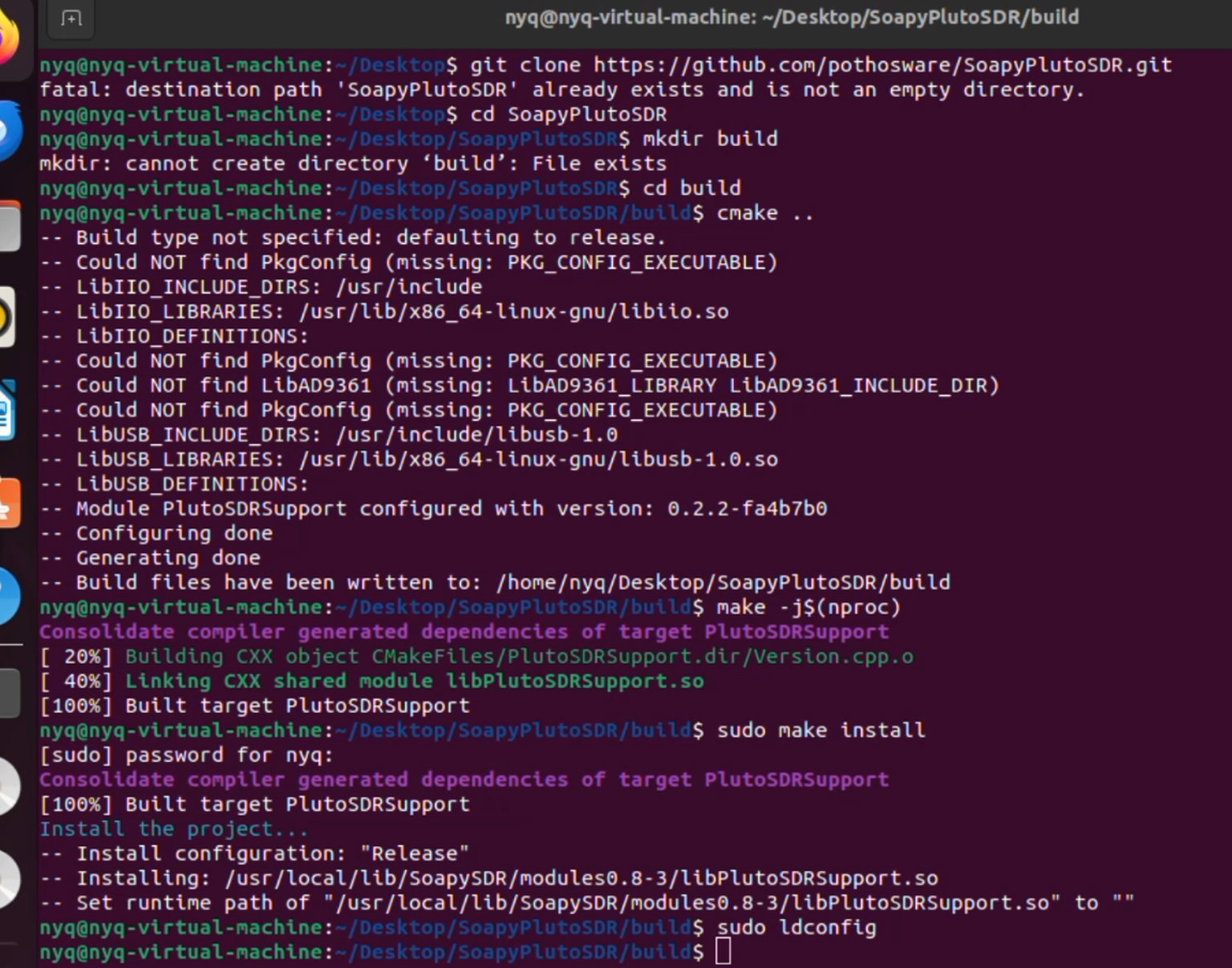
First, install the required dependencies before proceeding with the main application.
git clone https://github.com/pothosware/SoapyPlutoSDR.git
cd SoapyPlutoSDR
mkdir build
cd build
cmake ..
make -j$(nproc)
sudo make install
sudo ldconfig
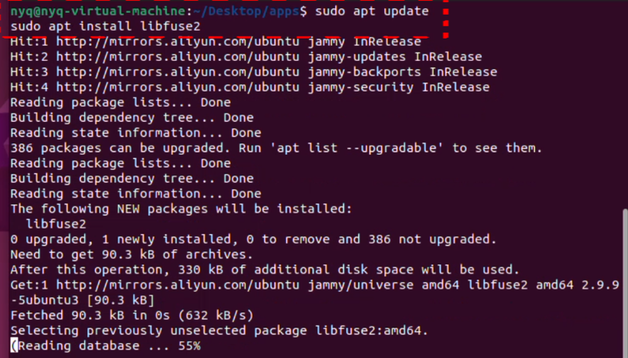
sudo apt update
sudo apt install libfuse2
Go to this website https://github.com/gqrx-sdr/gqrx/releases to download the latest Gqrx binary file.
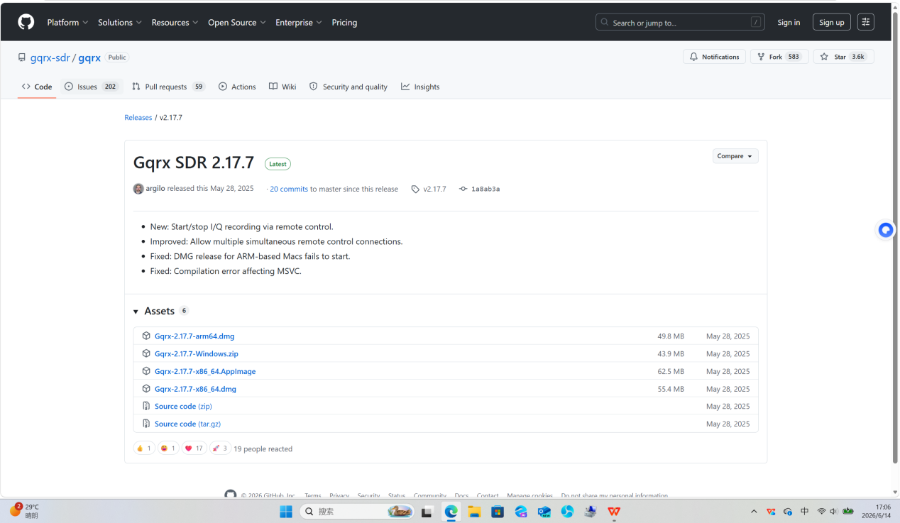
Place the downloaded Gqrx-2.17.7-x86_64.AppImage from the official website into the apps folder on your desktop. Open a terminal and run the command below to navigate to this directory:
cd ~/Desktop/apps
Note: If the file is stored in a different location, replace the command with the corresponding actual path.
Grant executable permissions to the program file Gqrx-2.17.7-x86_64.AppImage to allow the system to run it.
chmod +x Gqrx-2.17.7-x86_64.AppImage
Create a system symbolic link
Run the following command to create a symbolic link, so you can launch the program directly from the terminal:
sudo ln -sf /home/nyq/Desktop/apps/Gqrx-2.17.7-x86_64.AppImage /usr/bin/abc
This command creates a symbolic link named abc in the system global directory /usr/bin/ pointing to the Gqrx executable located in the apps folder on your desktop. After configuration, you can launch Gqrx quickly by entering abc or the full filename in the terminal.
Using Gqrx to receive FM radio broadcasts
At this point, take the Pluto Sky R2 as an example. Connect the device to the computer with a USB cable and plug the antenna into RX1.
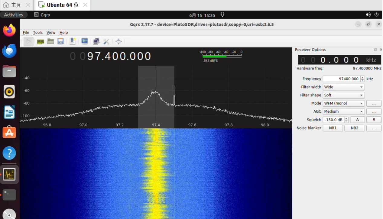
Launch Gqrx and select PlutoSDR as the device. If the device is not detected, choose Other in the Device menu, enter ip:192.168.2.1 in the Device string field, then click OK.
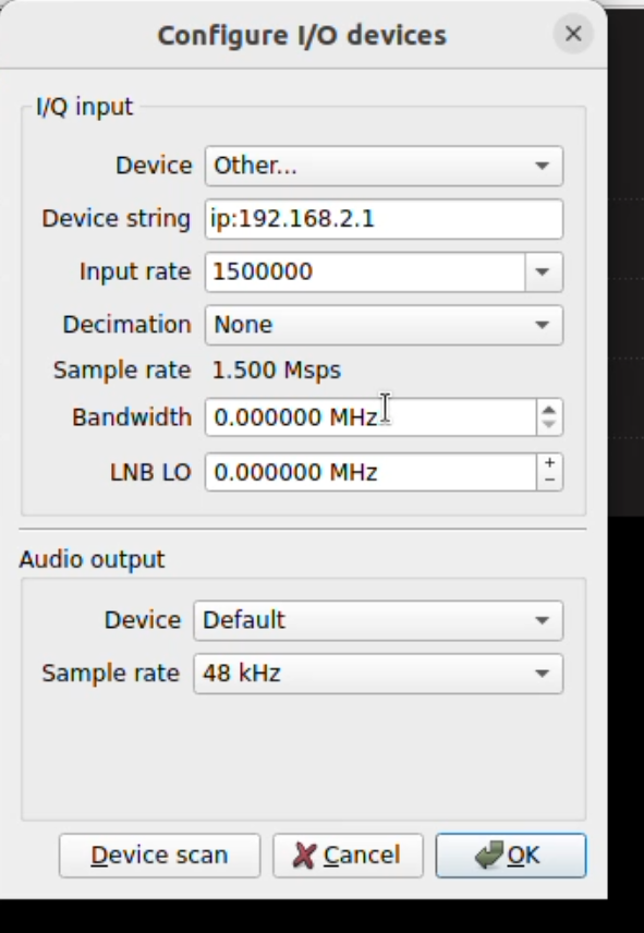
The title bar at the top of the software displays device=PlutoSDR,driver=plutosdr,soapy=0,uri=usb:3.6.5, which indicates the PlutoSky R2 hardware has been successfully recognized via USB, eliminating the need to reselect the device. In the Frequency input box on the right panel, enter the target FM radio frequency point of 97400.000 kHz (equivalent to 97.400000 MHz). For Filter width, select Wide from the dropdown menu — this wide bandwidth complies with the domestic 88–108 MHz FM stereo broadcast standard of 200 kHz bandwidth, fully accommodating the full spectrum of FM signals. For Filter shape, choose Soft (soft roll-off filtering), which delivers smoother in-band waveforms and lower audio distortion. Under Mode, select WFM (mono) from the demodulation mode dropdown for wideband FM demodulation in mono, suitable for regular FM radio reception. Switch to WFM stereo mode if stereo audio output is required.
Click the play button to start listening to the radio.
Firmware Flashing Tutorial
PlutoSky R2 Firmware Operations Youtube Video
Three Boot Modes
There are three boot modes for the PlutoSky R2, JTAG boot mode, flash boot mode and sd card boot mode.
1.JTAG Mode: It is used for debugging and firmware flashing. It can flash firmware into the onboard Flash chip. Only JTAG mode supports flashing Flash firmware via VIVADO software in your computer. The PlutoSky R2 does not have DFU button. VIVADO flashing will erase Flash and DFU firmware, and the device will automatically enter into DFU mode after power-on. The DFU boot mode is used to recover when custom programs are flashed into the onboard Flash chip and cause firmware errors.
2.Flash Mode: Load boot files from onboard Quad-SPI Flash chip.
3.SD Card Mode: Load boot files from TF card which contains boot.bin.
The PlutoSky R2 supports both Flash boot and SD card boot by factory default.
DIP Switch Boot Mode Definition
Note: DIP switch settings must be operated when the device is powered off; settings are invalid under power-on state.
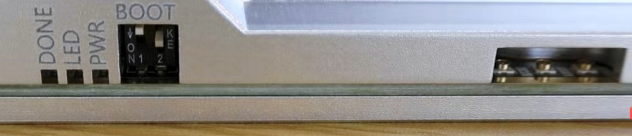
QSPI Boot Mode: Switch 1 connects to VCC 3V3, Switch 2 connects to GND. Factory default boot mode from onboard Flash.
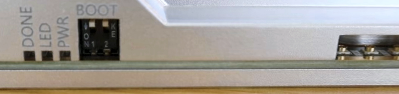
SD Card Boot Mode: Switch 1 connects to VCC 3V3, Switch 2 connects to VCC 3V3. Boot from microSD card with boot.bin.
JTAG Debug Mode: Switch 1 connects to GND, Switch 2 connects to GND. Used for development debugging and firmware burning.

After setting the DIP switch, connect the PC to the Debug USB port with a data cable. The red POWER LED will light up after power-on.
When using SPI Flash firmware (QSPI boot mode): If you need to enable the external 40MHz clock, you must power off the device first, then use a jumper cap to short the corresponding pin area. The internal/external clock cannot be switched via GPIO.
When using microSD card firmware (SD boot mode): After switching to SD card boot via DIP switch, you can use GPIO pins to switch internal and external 40MHz clocks at any time, no repeated jumper operation is needed.
SD card firmware burning
If you want to use the SD card boot working mode, you need to do this sd card firmware flashing.The SD card firmware used is located in the folder: Pluto \SD Card Firmware
SD Card Burning Steps
Use a TF card and format it as FAT32 file system.
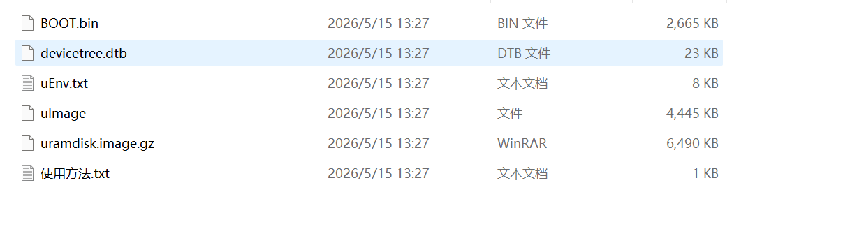
Copy all firmware files to the root directory of the SD card. We will provide the files need on our github wiki.
Power off the device, set DIP switch to SD card boot mode.
Insert the SD card into the device slot, connect device USB port to PC, then power on the device again.
Verify SD Card Firmware Startup
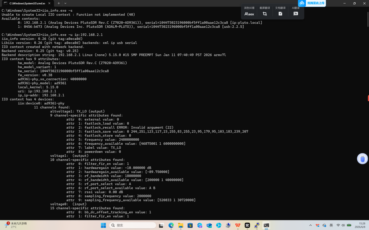
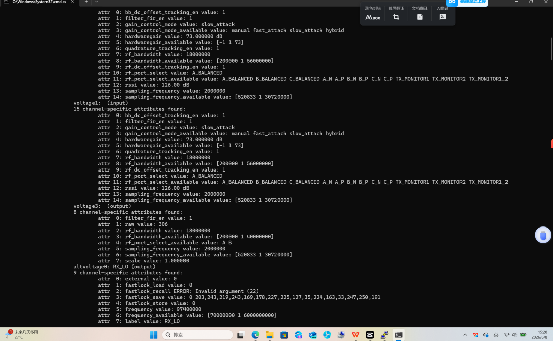
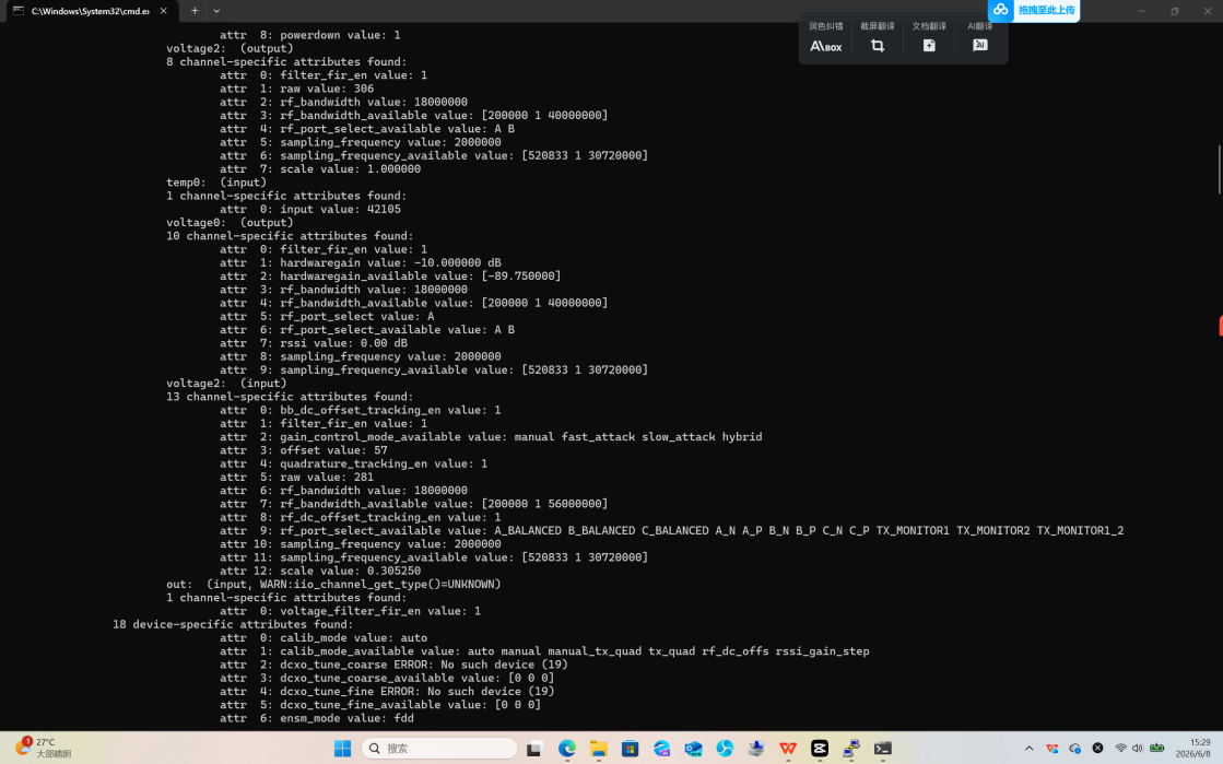
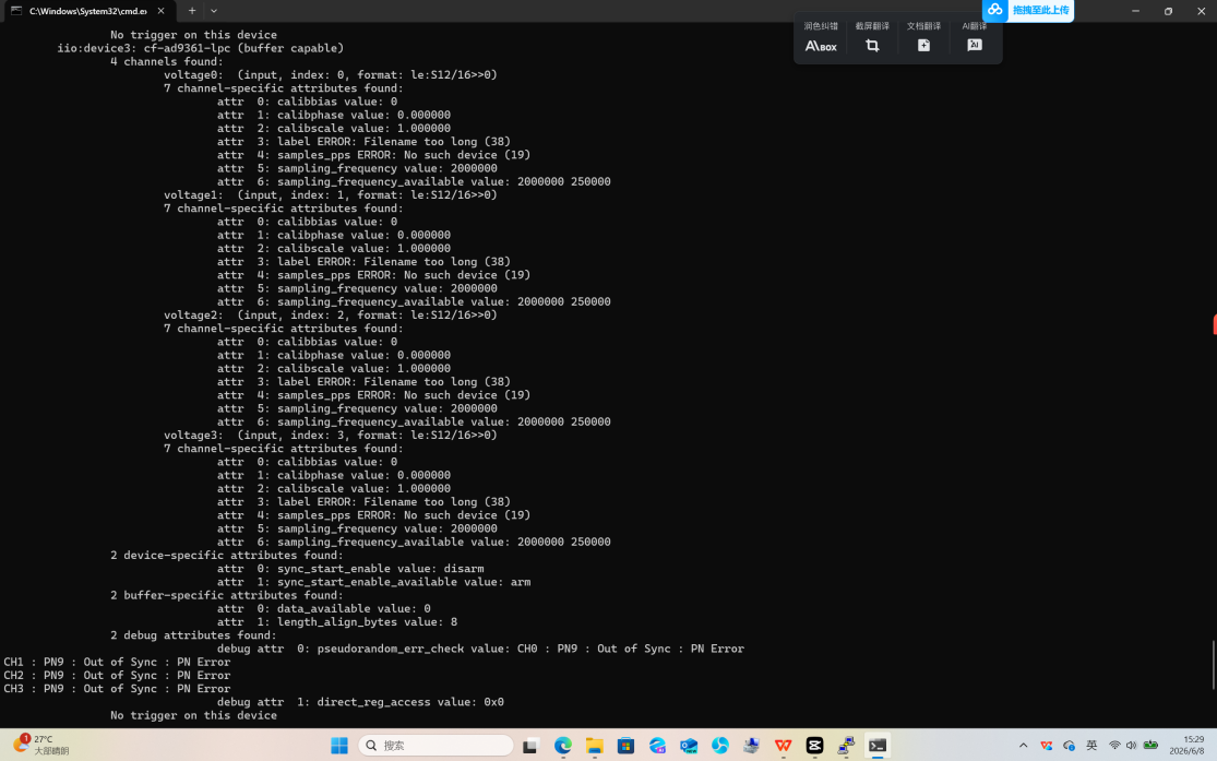
Method 1: Test via CMD command
Open CMD in the folder of iio_info.exe, input one of the following commands:
iio_info.exe -s
iio_info.exe -u ip:192.168.2.1 or iio_info.exe -u ip:pluto.local
Note that if you use the SD card boot mode, the default IP address of the PlutoSky R2 is 192.168.2.1. And you can also manually modify the IP address.
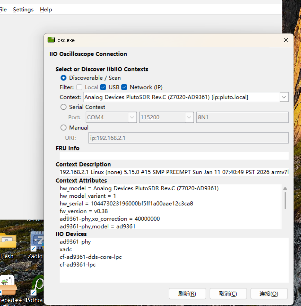
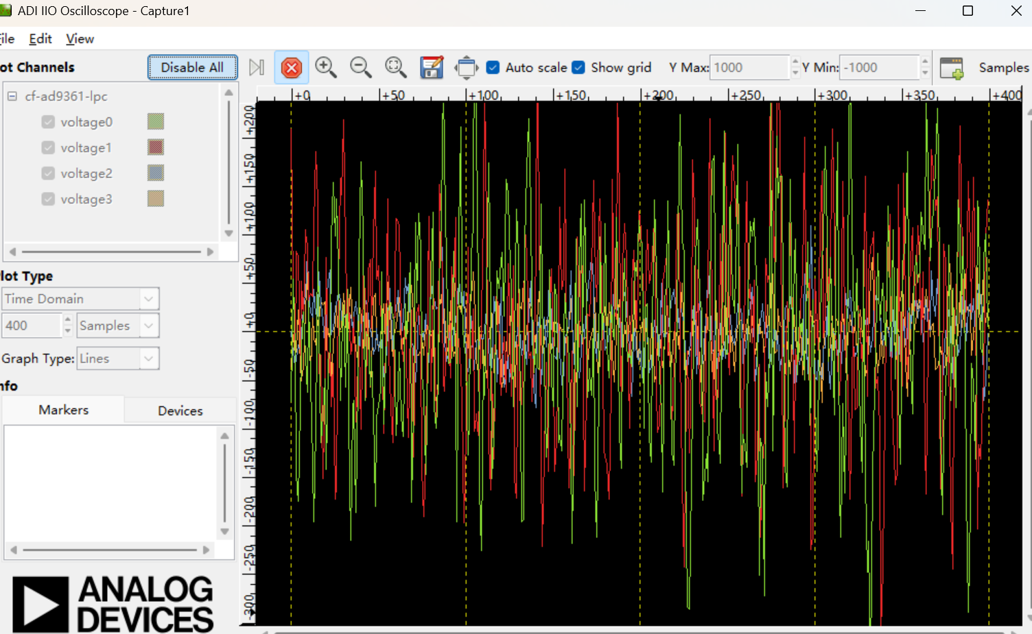
Method 2: Verify via IIO-Oscilloscope Software
Open IIO-Oscilloscope software, add new device, manually input IP: 192.168.2.1.
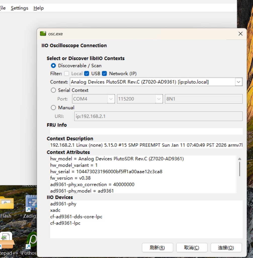
If the software recognizes AD9361 hardware and displays spectrum waveform, the firmware runs normally.
Flash Firmware via VIVADO in JTAG Mode
Note: The device is pre-burned with official firmware by factory default. Ordinary users do not need this operation.
This operation is only required when users use the board as a ZYNQ development board and flash custom programs, resulting in damaged and abnormal Flash firmware.
Enter JTAG Boot Mode
Power on the device in JTAG boot mode by switching the BOOT selector to JTAG when the device is powered off.
Hardware connection and power-on
Connect the PlutoSky R2’s DEBUG port to your computer via a Type C data cable. Power on the device; the POWER indicator will light up red.
Vivado Hardware Connection Operations
Launch the Vivado software → Click Open Hardware Manager → Wait for loading → Click Open target.
Solutions for Device Not Recognized by Vivado
If Vivado fails to detect the device: Navigate to .../nt64/digilent, run install_digilent.exe as Administrator, follow the wizard to install the driver, restart your computer, then reopen Vivado.
Configure Storage and Program Files
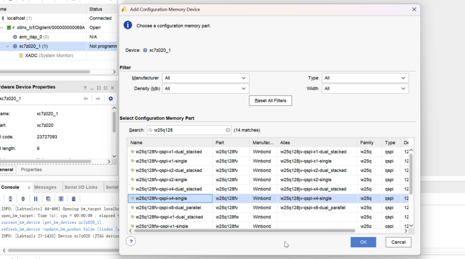
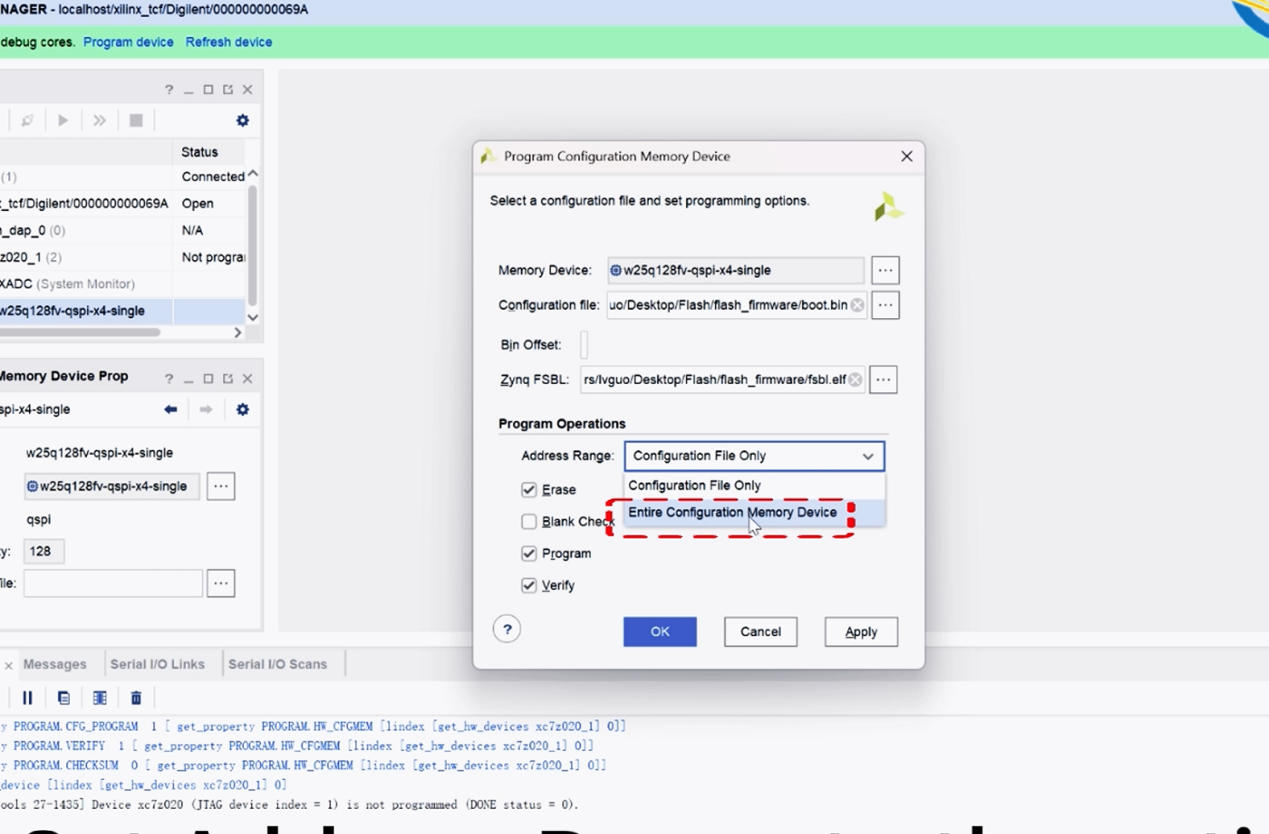
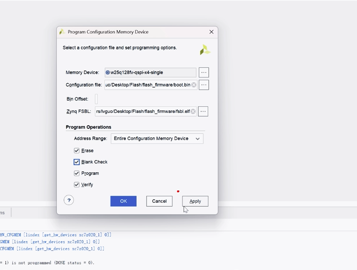
Once the device (e.g., xc7z020_1) is detected: Right-click and select Add Configuration Memory Device → Search for w25q128, select the x4 version and confirm → Import the provided boot.bin and fsbl.elf files → Set Address Range to the entire Flash → Check the 4 configuration options → Click Apply and wait 3-5 minutes for programming.
Then proceed with DFU firmware programming
Switch to Flash Boot Mode
Power off the device, switch the BOOT selector to Flash boot mode, then connect the device’s USB port to your computer via a data cable.
Verify the previous programming result
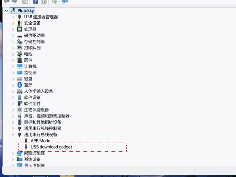
Open Device Manager on your computer; if USB download gadget appears under "Universal Serial Bus devices", the previous programming is successful. Otherwise, it means there was an error in the firmware flashing during the previous JTAG mode
Modify the path of the programming script
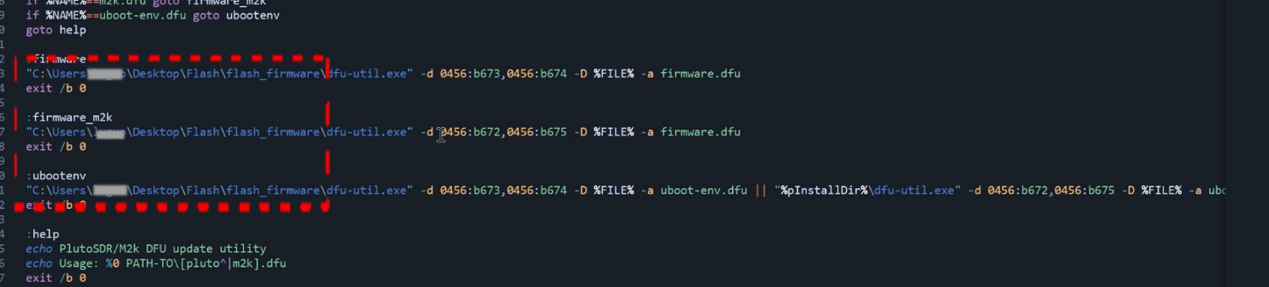
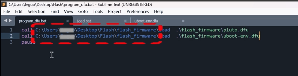
Open program_dfu.bat (in the programming folder) with Notepad++/Sublime Text. Only modify the file path before /Load (point to the location of pluto.dfu and uboot-env.dfu), save the file. Then modify the path in Load.bat in the same way.
Perform DFU programming and verification
Double-click program_dfu.bat and wait for automatic downloading via the command line. Reboot the device: programming is successful if the DONE LED is on and the LED blinks, or the device is detected in IIP Oscilloscope viaSetting→Connect.
Bricked Device Recovery Tutorial
Bricked Reason
The factory firmware has configured environment variables by source code, which hacked the AD chip from 9363 to 9361 by default.
If users manually execute hacked commands via Putty, repeated environment variable configuration may cause conflict and make the device bricked.
Recovery Steps
1. Preparation and Initial Setup
Format SD card as FAT32, copy BOOT.bin, devicetree.dtb, uEnv.txt, uImage, uramdisk.image.gz to SD card root directory.
Insert the SD card into the corresponding slot of the device.
Ensure the device is powered off, then switch it to the SD Card Boot Mode (adjust the mode switch according to the device hardware specifications).
Connect the DEBUG port of the device to the USB port of the computer using a compatible USB cable.
2. Connection Verification
After completing the connection, check the device indicators:
- The LED indicator flashes continuously.
- The DONE and PWR indicators remain steadily on.
If the indicators show as above, the connection is correct; otherwise, recheck the SD card insertion, mode switch and USB connection.
3. Serial Port Configuration and U-Boot Mode Access
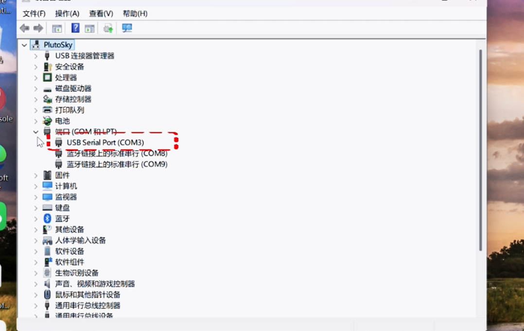
Open the Device Manager on the computer, locate the USB COM Port (record the port number, e.g., COM3, for subsequent configuration).
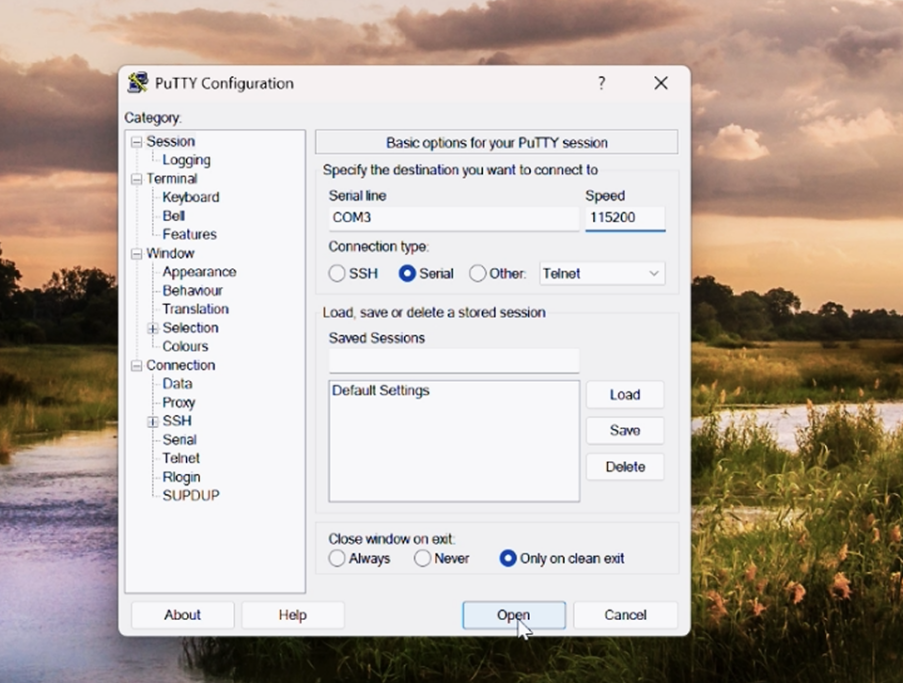
Launch the PuTTY software, and configure the serial port parameters as follows:
Connection Type: Select Serial
Serial Line: Enter the COM port number
Speed (Baud Rate): Set to 115200
Click the Open button to establish the serial connection.
Press the RST button on the device; the LED indicator will stop flashing immediately.
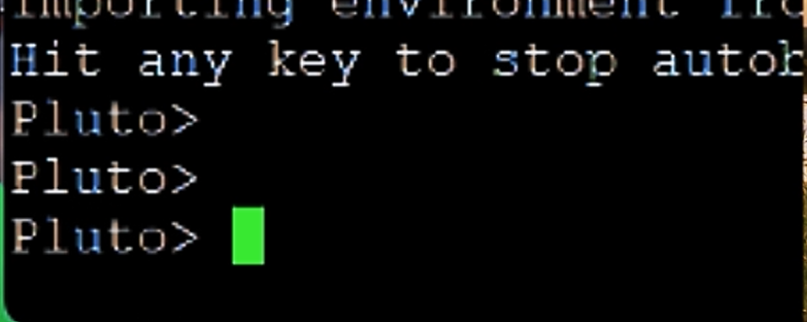
Press the Enter key on the computer keyboard, wait for 3-5 seconds. If the prompt Pluto> appears in the PuTTY terminal, it indicates that the U-Boot mode is successfully accessed.
4. Flash Erasure Operation
In the PuTTY terminal (under Pluto> prompt), enter the following commands in sequence, and press Enter after each command to execute:
sf probe
sf erase 0x0 0x1000000


Note: The erasure process takes approximately 2-3 minutes. Do not power off the device or disconnect the USB cable during the erasure process, otherwise the device may be damaged.
Unplug and reconnect the device to the USB port. Check if the device is recognized in Device Manager. If detected, the device has been restored successfully.
This operation erases all wrong custom configurations in onboard Flash to eliminate boot failure.
After OK is displayed, reconnect the device (unplug and plug it back in), open Device Manager, and check if the device is recognized.
Confirm Real Chip Model
Problem Description
The boot serial information displays 7010, but the actual hardware is Zynq-7020. The number 7010 is only a firmware identification string, it does not represent the real hardware model, and there is no hardware fault.
Verify Chip Model
Power off the device, set DIP switch to JTAG mode, connect JTAG interface to PC.
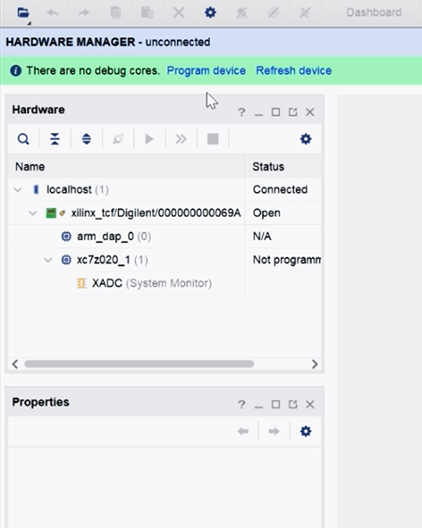
Open Xilinx Vivado, enter Hardware Manager and connect target device.
Vivado will automatically read and display the real chip model xc7z020 to confirm hardware correctness.
Reference
https://wiki.analog.com/university/tools/pluto/drivers/windows
https://github.com/analogdevicesinc/plutosdr-m2k-drivers-win/releases
https://wiki.analog.com/university/tools/pluto/prerequisites
https://wiki.analog.com/university/tools/pluto/users/firmware
The PlutoSDR supports USB 2.0 On-The-Go (OTG), and can be used in two different modes:
https://wiki.analog.com/university/tools/pluto
https://www.rtl-sdr.com/plutosdr-quickstart-guide/
https://wiki.analog.com/university/tools/pluto/users/quick_start
https://wiki.analog.com/university/tools/pluto/prerequisites
https://wiki.analog.com/resources/tools-software/linux-software/gnuradio
https://plutosdr.org/getting-started/
https://blog.csdn.net/goldenhawking/article/details/104072054
https://blog.csdn.net/weixin_42905573
https://blog.csdn.net/zhangxq0521/category_9812491.html
https://wiki.gnuradio.org/index.php/PlutoSDR_FMRadio
If you have any questions, please feel free to contact us at any time.
Follow our YouTube channel and you can access more video tutorials.
https://www.youtube.com/@OpenSourceSDRLab