
GNU Radio QPSK Modulation and Demodulation on PlutoSky P1
Learn QPSK modulation and demodulation with GNU Radio, from constellation simulation and packetized text transfer to a PlutoSky P1 SDR hardware link.

Experimental Preparation and File Structure
Hardware Checklist
Software Checklist
Experimental Files and Flow Graphs
Principles of QPSK Modulation
QPSK (Quadrature Phase Shift Keying) employs four complex carriers with distinct phases to represent four symbols. Each symbol carries 2 bits. Therefore, for an identical bit rate, the symbol rate of QPSK is half that of BPSK. The complex baseband symbols are expressed as:

The practical bit-to-symbol mapping is implemented by digital.psk_4()[1]. The constellation points lie on a single circle in the complex plane; all four points share the same amplitude with a phase separation of 90°. Although its constellation geometry resembles that of 4QAM, the mapping and modulation interpretation follow the definition of phase-shift keying for QPSK.
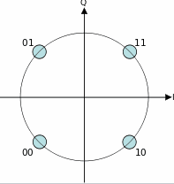
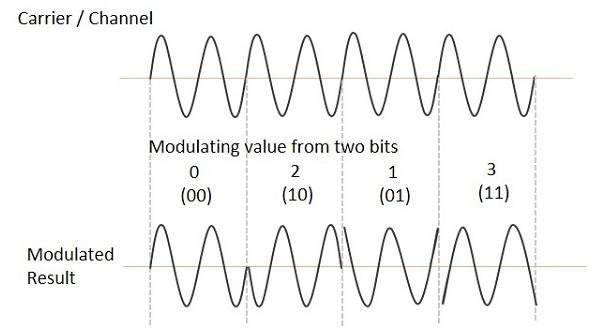
QPSK four-point constellation diagram: each two-bit symbol corresponds to a different carrier phase.
Simulation of QPSK Modem Using GNU Radio
Flow Graph Loading and Verification
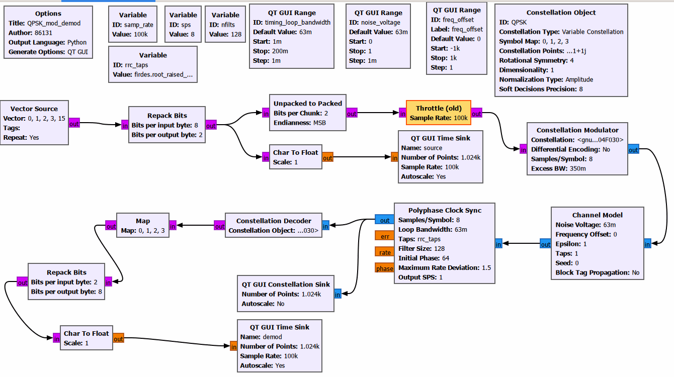
Open QPSK_mod_demod.grc. In the transmit chain, the vector source generates test byte sequences. The bit repacking block splits each 8‑bit byte into 2‑bit QPSK symbols. The Unpacked to Packed block rearranges the bit stream, and the Throttle (old) block controls the flow rate, before the signal is fed into the constellation modulator to generate the QPSK complex baseband signal. A parallel branch from Char To Float to QT GUI Time Sink is used for time-domain waveform observation and does not affect the main modulation link.
After passing through the channel model where noise and frequency offset are added, the modulated signal enters the receiver chain. It sequentially goes through polyphase clock synchronization, constellation decoding, symbol mapping and bit repacking to recover the original bytes.
Analysis of Simulation Results
After execution, the source time-domain window displays the repacked QPSK symbol sequence, and the demod window shows the symbol sequence recovered after synchronization and demodulation.
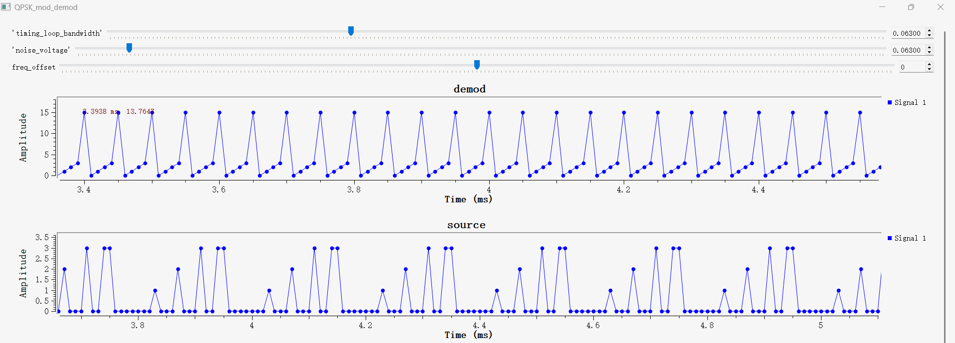
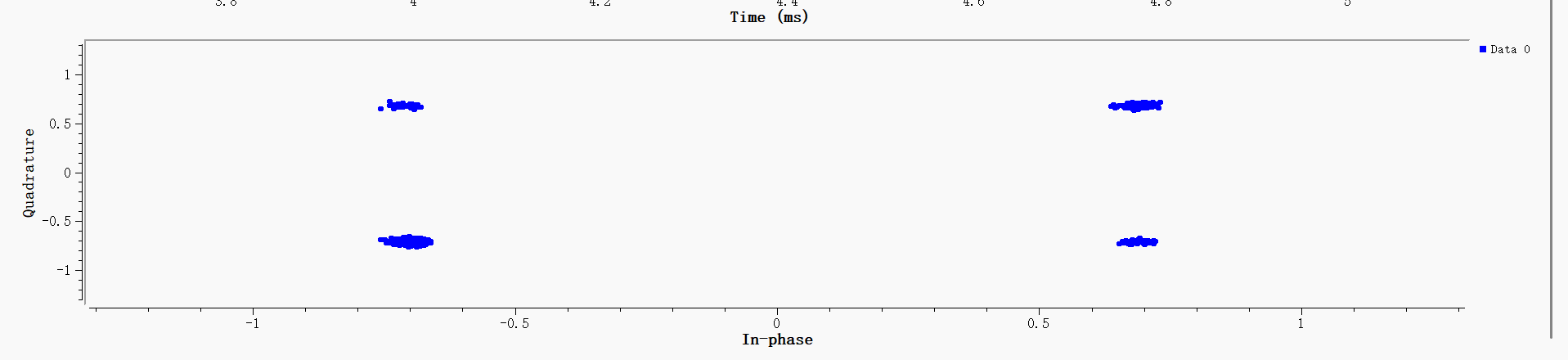
The upper plot group contains two time-domain waveforms: the demod trace is the recovered baseband sequence after QPSK demodulation, while the source trace is the original transmitted bit sequence. The symbol edges of the two sequences align properly, indicating that the polyphase timing loop is locked and symbol timing is recovered correctly. The lower plot is the QPSK constellation diagram after demodulation. Four distinct, tightly clustered constellation clouds can be observed. The well-converged constellation points verify that the symbol timing recovery module works properly.
QPSK Text Transmission Simulation Based on GNU Radio
Transmitter and Receiver Link
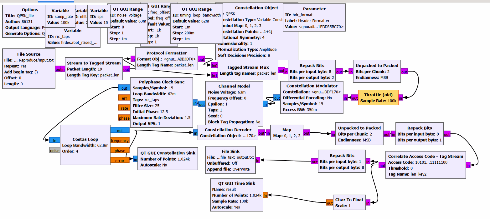
Open QPSK_file.grc. The File Source reads text data from input.txt; Stream to Tagged Stream segments the input stream into 19-byte data packets; Protocol Formatter generates packet headers; Tagged Stream Mux concatenates the headers and payloads. The stream then undergoes 8-bit to 2-bit bit repacking and QPSK modulation, and passes through a channel model with additive noise. At the receiver, polyphase clock synchronization (PFB), Costas carrier synchronization, and constellation decoding are carried out. The 2-bit symbols are converted back into 8-bit bytes, and the recovered byte stream is finally written to QPSK_file_text_output.txt.
Text Transmission Results
Run the QPSK_file.grc flowgraph and stop it after approximately 4.1 seconds. The output file QPSK_file_text_output.txt is created in the working directory. After the synchronization loop locks, the recovered text can be observed in the file:
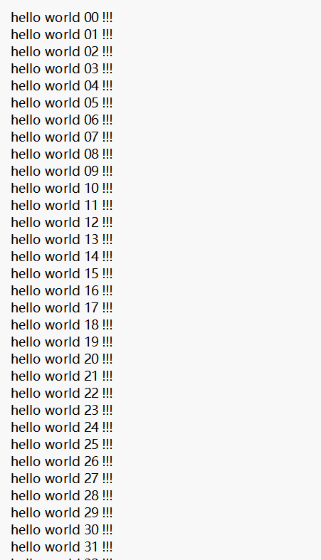
The recovered content matches the original text stored in input.txt. It verifies that the complete chain including packet framing, QPSK modulation, noisy channel transmission, timing & carrier synchronization, demodulation and byte reconstruction works correctly, and reliable text transmission via QPSK is realized.
QPSK Text Transmission: PlutoSky P1 Transmitter and Receiver
Integrated Flowgraph for PlutoSky P1
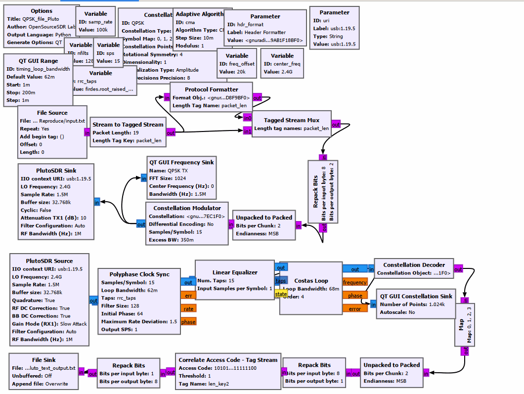
Open QPSK_file_Pluto.grc. On the transmitter side, text data is read from input.txt and processed with frame formatting, QPSK symbol mapping and root-raised-cosine (RRC) pulse shaping before feeding into the PlutoSDR Sink. On the receiver side, complex baseband samples are acquired from PlutoSDR Source. The signal goes through PFB clock synchronization, linear equalizer with CMA adaptive algorithm, 4th-order Costas loop, QPSK constellation decision, access code correlation and byte reassembly. Finally, the recovered byte stream is written to QPSK_file_Pluto_text_output.txt.
Result Analysis
Wait for transmission to finish, locate the output file QPSK_file_Pluto_text_output.txt and open it with Notepad for inspection.
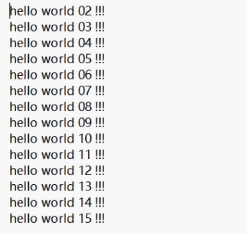
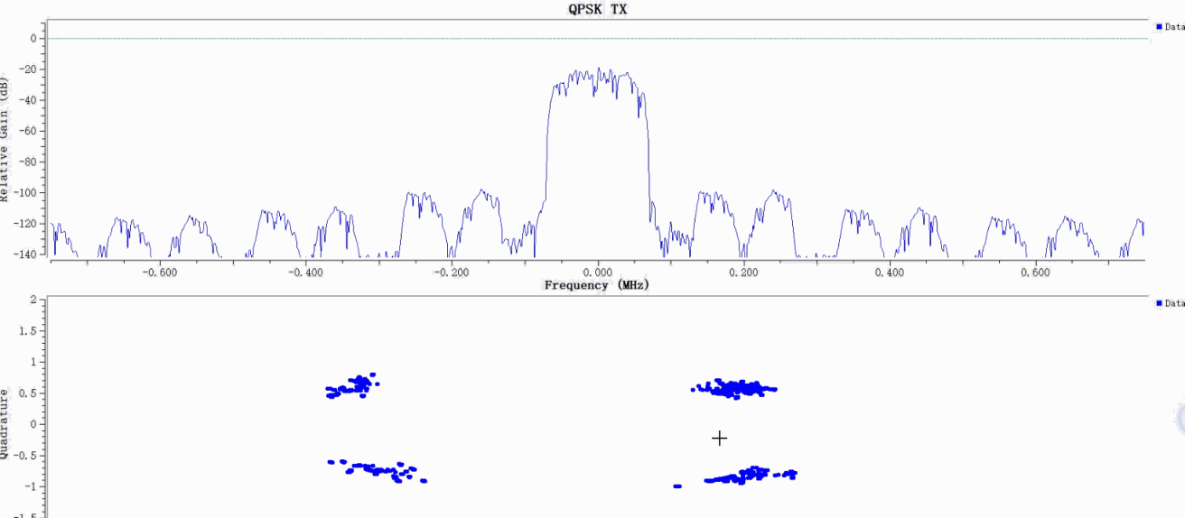
The demodulation of the measured link is normal. The output file can completely restore the input hello world text sequence from the transmitter. Frame tag transmission, clock synchronization, carrier recovery, equalization and frame acquisition modules all operate stably. The function of the entire QPSK communication link is verified